For our ECE 4760 final project, we designed and built a running band that provides feedback to users with temperature and vibration.
This provides an unique way to monitor running habits with temperature feedback. The running band attaches to a user’s upper arm and counts the number of steps the user takes. It then determines whether or not the user is moving at a desired cadence. The band produces a cold sensation when the user is not moving fast enough. The band vibrates if the user continues to be slow.
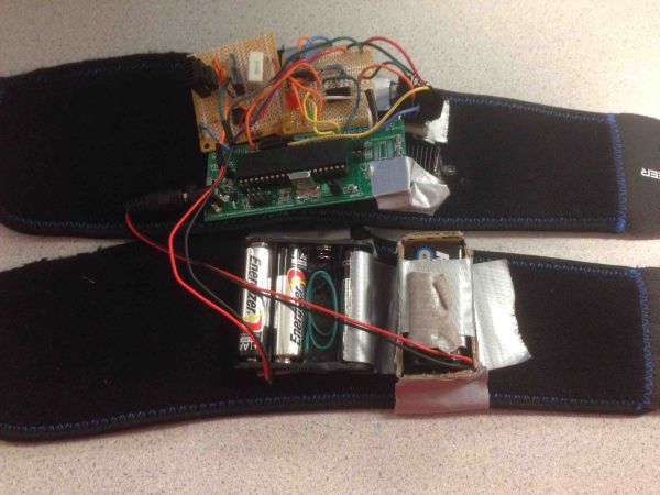
The band runs from an Atmel ATmega1284P microcontroller, a Peltier Plate, vibration motor, and various control circuits. Users operate a switch to determine if they want the band to operate in running or walking mode.
High Level Design
Overview
This project was developed by using our knowledge of microcontrollers and hardware design. We ran our device using an Atmega1284p device and attached devices such as a voltage regulator to control voltage from a battery pack, Peltier plate and vibration motor controlled by PWM and amplifier circuits and an accelerometer to measure rate of movement. We came up with the idea because it was a good way to monitor exercise while intuitively providing feedback to the user through temperature and haptic feedback.
Logical structures
Our device operates first by taking in information from an accelerometer. This data provides information on the current acceleration of our device in two directions. Using this data, the device determines when there has been a massive change in acceleration, which we can say happens roughly when the user takes a step. Using this information, we estimate the user’s current steps-per-interval (interval chosen to allow for adequate time to make an estimation). We compare this estimated steps-per-interval to one of two thresholds (walk or run) that is set by the user using a switch on the device. Either a red or green LED will light up depending on whether the device is in run (red) or walk (green) mode. The thresholds are set in the beginning during a 15 second delay period that also acts as a calibration period. The user’s threshold is set during this time. If the steps-per-interval is lower than the threshold, we turn on a Peltier plate that cools the side that is in contact with the user.Once the user has increased the steps-per-interval to above the threshold, the Peltier plate will be turned off. If the user’s steps-per-interval stays beneath the threshold for too long, a vibration motor will activate for a small period of time to give further feedback. If the steps-per-interval is higher than the threshold, we send three quick bursts from the vibration motor.
Standards
Though we did not find any official standard for the temperature for which extended temperature contact is safe, we found a reasonable metric from a NASA paper. The paper said that an extended period of -18°C(0°F) Celsius should be the cold threshold for unlimited contact. Our cold plate definitely does not reach this temperature. Though the warm side of the Peltier plate should not be touching the user’s skin, it is still important to keep it on a temperature that would not harm the user if the user accidentally touches it. 45°C (113°F) is painful to touch for any period of time. We do not believe our Peltier plate hot side should reach these temperatures.
Relevant Patents and Copyrights
While working on this project, we found a couple of patents that could be similar to our design. These are Tactile feedback in an electronic device and Temperature feedback motion controller. The patent, Temperature feedback motion controller. is especially similar. However, this patent is used for controllers, especially video games, whereas our project is used for running or walking. The other patent, Tactile feedback in an electronic device could be applied to our project, but because it is worded so vaguely, we do not think our project infringes upon any intellectual property.
Hardware and Software Tradeoffs
The first major hardware and software tradeoff we made in our design was to use an analog accelerometer rather than an SPI protocol driven accelerometer. The advantage of this method was that we did not need to worry about following the SPI protocol and adhering to the restrictions it may provide. To use the analog accelerometer, we just needed to use the ATmega1284’s built in analog to digital converter to get values from the signal received from the accelerometer. The downside to this tradeoff is that a SPI protocol controlled accelerometer may have given us more precise and structured results, but the design of our device did not require such precision so this tradeoff was acceptable.
A second tradeoff that we made for the device was to put the noise control of our device in the software part of the design. This meant that we put logic in our code to take out noise that may occur from a sudden change in acceleration that might cause the device to count extra steps that were not there. To make the software less complicated, we could have attempted to put the signal through a low pass filter of some kind, but we believed that a software solution would be easier to implement.
User Interface
The most simplistic human control feature was the on/off switch. It simply controls whether to turn the system on or off.
A second human interface feature was a SPDT switch on the device that allows the user to set the steps-per-interval threshold to be a lower value for the walk mode or a higher value for the run mode. This allows the user to decide between two different options for a workout.
The third and most major human interface with the device is the accelerometer and haptic feedback system. The accelerometer reads the rate of movement from the human user and adjusts the vibration motor’s rate of vibration and the Peltier plate’s temperature to give feedback to the user to inform him that he is not running or walking fast enough.
The Accelerometer
The steps-per-interval value that we use to determine the rate of motion of the user is found through the acceleromter. The accelerometer gives three analog signals, one for each of the three accelerations in the x,y and z direction. However, we found that we only needed two of these directions to draw accurate results, so we chose the two directions that are easiest to read from when we mount the accelerometer on the user’s arm (x and y).
The Peltier Plate
The Peltier plate is a plate that gets hot on one side and cold on the other depending on the direction and amount of current that we put into it. We had to make sure that the plate got cold enough such that the user can feel the cool side easily. However, when going to temperatures that low on one side, the other side gets equally hot, so we had to ensure that the heat from the hot side did not conduct to the cold side. To do this, we had to put a heat sink on the Peltier plate. This heat sink had to be attached with thermal adhesive that would not become loose when temperatures change.
The Peltier plate gets its cooling/heating function through a phenomenon named the Peltier effect, a type of thermoelectric effect. A thermoelectric effect is one that converts voltage provided into a difference of temperature. This effect was perfect for the device we wanted to create since it does not require any outside substance for a cooling effect other than the Peltier plate, which can be easily hooked up into our circuit. The polarity of the voltage or the flow of current is what decides which side of the Peltier plate gets hot and which side gets cold. A Peltier plate is constructed out of two conductors connected by a junction that removes or adds heat to one of the conductors and does the opposite to the other.
Furthermore, to control the temperature of the Peltier plate, we needed a PWM controlled current source. To do this, we used an optoisolator to keep the Peltier plate circuit separated from the microcontroller unit so that we would not damage the mcu if something went wrong with the Peltier plate. We also used a BJT to control the current going into the Peltier plate based upon the PWM.
Because this device is supposed to attach to your arm and the Peltier plate draws a lot of current, we needed to use a separate battery pack to power this part of the system that does not power the microcontroller. We used three AAA batteries and used a voltage regulator to get the desired voltage needed for the system.
The Peltier plate was given a max of about 0.7 Amps in our circuit. With a resistance of about 1 Ohm (given im the data sheet), we expect about 0.7 V to be across the Peltier plate during use. Because of the circuit it was connected to, we observed the Volts across the Peltier plate to be more around 0.5-0.6 Volts using a multimeter. This corresponds to about a 30 degree Celsius temperature differential. From what we observed, this was roughly the case with the colder side being around 10 degree Celsius and the warm side being around 40 degree Celsius. This adheres to the safety standard since the cold side is definitely not in the danger zone and the warm side is heat sinked so prolonged contact should not hurt since we want it to be below 45 degrees Celsius, which it is.
Hardware
Hardware Overview
This project requires hardware to be built to control the external components such as the Peltier plate, vibration motor, etc. The Peltier plate control circuit is composed of a BJT, optoisolator and the Peltier plate. Furthermore, a voltage regulator is important to ensure the rail voltage for the Peltier plate is properly set. The vibration motor control circuit is important to allow a PWM to control it. The LED and switch component is also necessary to allow for the switching of modes. Finally, the accelerometer itself is attached to resistors to connect to the microcontroller ports.
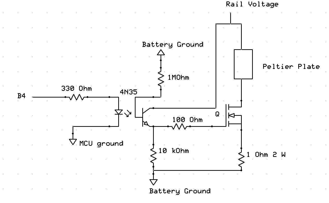
Peltier Plate Control Component
The Peltier plate control component is run by a PWM. In our device, we send the controlling PWM from port B4 for the Peltier control. This PWM is sent to a 4N35 optoisolator, connected to a 330 ohm resistor. An optoisolator was chosen to protect the MCU from anything that the Peltier plate may do to damage it. The output of the optoisolator will then go into a TIP31 BJT. This TIP31 BJT acts as the voltage controlled current source that provides the necessary current to turn on the Peltier plate. A TIP31 was chosen because it was better rated to allow for this type of current control. To ensure that the TIP31 does not get too hot because it might be dangerous to place on somebody, we lowered the input resistance to the TIP31’s base to be roughly 100 ohm. We also used a 1 ohm 2W rated resistor to connect the TIP31’s emitter to ground to allow the collector current to be as high as necessary to run the Peltier plate. We determined that a current of roughly 0.68 A was good enough to allow the Peltier to be noticeably cold. A schematic can be seen in Appendix B.
The voltage rail for the voltage controlled current source needed to be 2.5 V. However, using just AA batteries, we could not get this voltage. To address this, we used a voltage regulator. For this purpose, we used a PQ30RV31 voltage regulator. This regulator takes in a voltage of 4.5 volts (3 AA batteries) and outputs a voltage of 2.58 V. A schematic can be seen in Appendix B.
Vibration Motor Control Component
The circuit for the vibration motor control component has two main parts, the BJT and the motor. We referenced a circuit that allowed us to use a PWM to control the vibration motor. This circuit is shown in Appendix B. The base resistor to the BJT was chosen to be 1 kOhm. To protect against possible voltage spikes that might occur from the motor, there is a 1N4001 diode placed across the motor as well as a small resistor in series with the motor.
Threshold Switch and LED Component
We wanted to allow the user to choose between a walking mode and a running mode. To do this, we used a SPDT switch. Since we have our microcontroller looking for an active low, we hooked the middle pin of the switch to ground and the two side pins of the switch to micrcontrollers pin D3 and D4. We then poll these pins frequently to determine which mode the users want to be in. To allow the user to see which mode he is in, we also have two LEDs (one green and one red) connected to ports C0 and C1, each through a 330 ohm resistor to control the amount of current flowing through. If the red LED lights up, the user is in run mode. When the green LED lights up, the user is in walk mode. A schematic can be seen in Appendix B.
Parts List:
| art | Source | Unit Price | Quantity | Total Price |
|---|---|---|---|---|
| Vibration Motor | Adafruit | $1.95 | 1 | $1.95 |
| Thermal Paste | Amazon | $8.00 | 1 | $8.00 |
| 9V Battery | Anywhere | $2.00 | 1 | $2.00 |
| AA Battery | Anywhere | $0.00 | 3 | $0.00 |
| Peltier Plate | Digikey | $14.84 | 1 | $14.84 |
| Mega1284 | ECE 4760 Lab | $5.00 | 1 | $5.00 |
| AA Battery Holder | ECE 4760 Lab | $0.00 | 1 | $0.00 |
| Voltage Regulator | ECE 4760 Lab | $0.00 | 1 | $0.00 |
| NPN Transistor | ECE 4760 Lab | $0.00 | 1 | $0.00 |
| Resistors | ECE 4760 Lab | $0.00 | 13 | $0.00 |
| Capacitors | ECE 4760 Lab | $0.00 | 1 | $0.00 |
| MOSFET | ECE 4760 Lab | $0.00 | 1 | $0.00 |
| SPDT Switch | ECE 4760 Lab | $0.00 | 1 | $0.00 |
| LED | ECE 4760 Lab | $0.00 | 2 | $0.00 |
| Optoisolator | ECE 4760 Lab | $0.00 | 1 | $0.00 |
| Header Pin | ECE 4760 Lab | $0.05 | 23 | $1.15 |
| Accelerometer | Modern Devices | $10.95 | 1 | $10.95 |
| Heatsink | Previously Owned | $0.00 | 2 | $0.00 |
| Elbow Pad | Target | $12.95 | 1 | $12.95 |
| Total | $56.84 |
For more detail: ColdRunner – A Temperature Feedback Running Band