Summary of COMPUTER CONTROLLED 8-CHANNEL DIMMER CIRCUIT
This article describes a computer-controlled 8-channel dimmer circuit using an AT90S2313P (ATTiny2313) microcontroller. The system receives commands via an RS232 port and detects mains zero-crossing to generate 100 Hz PWM signals. These signals drive MOC3021 opto-triacs, enabling individual control of eight 200W loads. The project includes source code in assembly and C++, along with PCB diagrams and a Windows XP-compatible PC program.
Parts used in the Computer Controlled 8-Channel Dimmer Circuit:
- AT90S2313P (ATTiny2313) microcontroller
- MOC3021 opto-isolated triac driver
- RS232 communication port
- PWM signal generator (100 Hz)
- Zero crossing detector
- PC running Windows XP
- Assembly source code (rs232dimmer.asm)
- Hex file (rs232dimmer.hex)
- Visual Basic project files (dimmer.vbp, dimmer.vbw, dimmer.frx)
AT90S2313P 200 watt dimmer circuit is controlled from RS232 port with MOC3021 opto isolated triac driver control program running on xp pretty simple hex to asm code pcb diagram AT90S2313P. There have also dosyalarıda… Electronics Projects, Computer Controlled 8-Channel Dimmer Circuit 200W AT90S2313P”avr project, microcontroller projects, “
AT90S2313P 200 watt dimmer circuit is controlled from RS232 port with MOC3021 opto isolated triac driver control program running on xp pretty simple hex to asm code pcb diagram AT90S2313P. There have also dosyalarıda pc program source code. Rs232dimmer.asm, rs232dimmer.hex, dimmer.vbp, dimmer.vbw, dimmer.frx
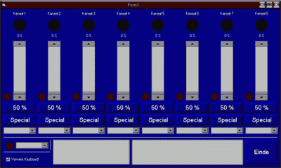
PC CONTROLLED DIMMER CIRCUIT
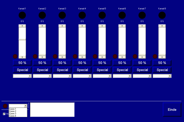
8 channel mains dimmer
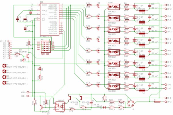
The heart of the dimmer is a ATTiny2313. the AVR performs three tasks: – It receives new data via the com port, – He receives pulses and the power of positive to negative goes and vice versa, this is called the zero crossing. – He makes 8 pulse-width modulated signal (PWM) with a frequency of 100 Hz. These signals are equal to the zero crossings from the mains.
The PWM signals control 8 optotriacs. These are optocouplers but with a built-in low power triac which can switch. In this project be MOC3021 optocoupler used. You can also add other optotriacs use as long as they have no zero-crossing detection. Because working not if you want dim.
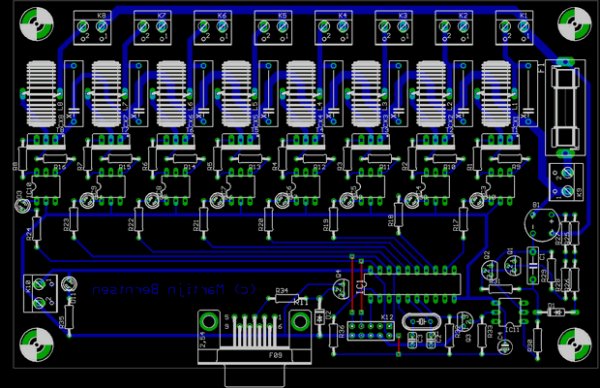
source: COMPUTER CONTROLLED 8-CHANNEL DIMMER CIRCUIT Computer Controlled 8-Channel Dimmer Circuit pcb schematic avr source code pc program alternative link: computer-controlled-8-channel-dimmer-circuit-200w-at90s2313p.rar
- How is the dimmer circuit controlled?
The circuit is controlled from an RS232 port with a control program running on Windows XP. - What is the role of the AT90S2313P microcontroller?
The microcontroller receives data via the com port, detects zero crossings, and generates 8 pulse-width modulated signals. - Does the project use zero-crossing detection for all dimmers?
No, the MOC3021 optocoupler used does not have zero-crossing detection, which allows for proper dimming functionality. - What frequency are the PWM signals generated at?
The microcontroller makes 8 pulse-width modulated signals with a frequency of 100 Hz. - Can other optotriacs be used instead of the MOC3021?
Yes, you can add other optotriacs as long as they do not have zero-crossing detection. - What files are included in the project source code?
The project includes Rs232dimmer.asm, rs232dimmer.hex, dimmer.vbp, dimmer.vbw, and dimmer.frx files. - How many channels does this dimmer circuit support?
This is an 8 channel mains dimmer circuit. - What happens if an optotriac with zero-crossing detection is used?
The project will not work correctly for dimming if you use an optotriac with zero-crossing detection.