My 6 year old son likes to sleep with the lights on. Eventhough I fitted his bed side lamp with a 4 Watt led bulb , I still thought I needed a way to control the lamp without getting up in the middle of the night and manually switching the lamp off.
I like to tinker with electronics and I had some wemos D1 esp8266 compatible boards lying around, a relay switch (from a 37 sensor kit bought for my Arduino compatible board), and thought about using them to control the lamp wirelessly with the use of a web server.
The build is straight forward, but fitting them in the project box, proved quite a task.
Step 1: Requirements
You will need:
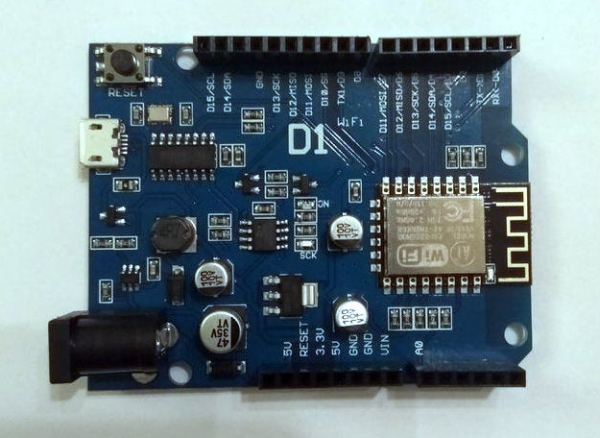
– Some sort of esp8266 board or I suppose and Ethernet capable Arduino. I got mine from Aliexpress searching for wemos d1. Eventually I got a compatible board, but it works, so no big deal.
– An on-on rocker switch, or on-off-on rocker switch. Take note that the switch must support at least two on states and should have at least 3 pins. The first rocker switches I bought had three pins but one of them was used to light a led inside the switch to indicate power. The one I eventually ended up using is an on-off-on one and thus the off state is unused, but again no big deal (I’ll change it in the 2nd revision!)
– A usb charger. I suppose you have some lying around. I opened it up and got the circuit board from inside.
– A typical Arduino relay (Aliexpress)
– A short Usb to micro Usb cable
– A project box (I used a 10cm x 10 cm x 3 cm (The Wemos compatible is around 6x7cm)
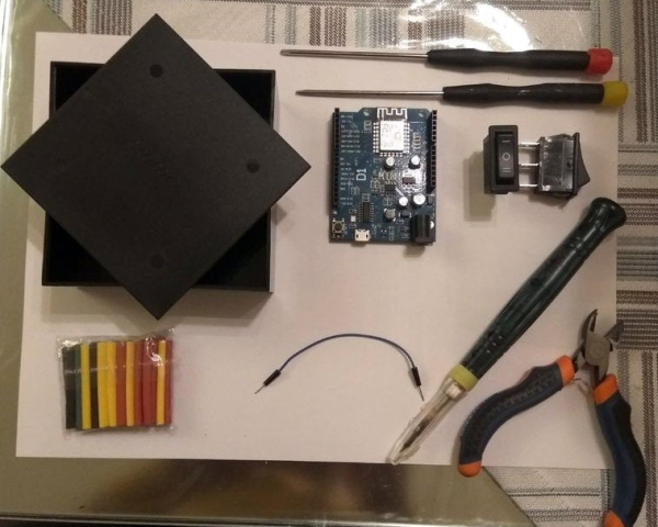
– Wire, some nuts and bolts, jumper wires, screwdrivers, hot glue, wire cutters, shrink tubing etc.
Step 2: The Hardware Sketch
You will need a circuit that has the “ability” to provide 4 states, because the user can interact with the lamp in four ways:
The user switches the light On or off manually , or On-Off via Wifi
So the states are:
Switch: ON , Relay: ON
Switch: ON , Relay: OFF
Switch: OFF, Relay: ON
Switch: OFF, Relay: OFF
That way you can interact with the lamp independently (eg if the Wemos doesn’t work you can still use the switch and vice versa)
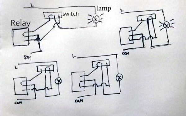
A rough sketch is shown (sorry about the quality). On the left is the relay, and on top the switch. The sketch shows the 4 states we need
Step 3: The Hardware Build
Since I wanted to make the box “self sufficient”, I had to clip both wires coming from the mains and connect the usb charger. It doesn’t matter which lead you connect from the mains to which lead of the charger because we use AC current.
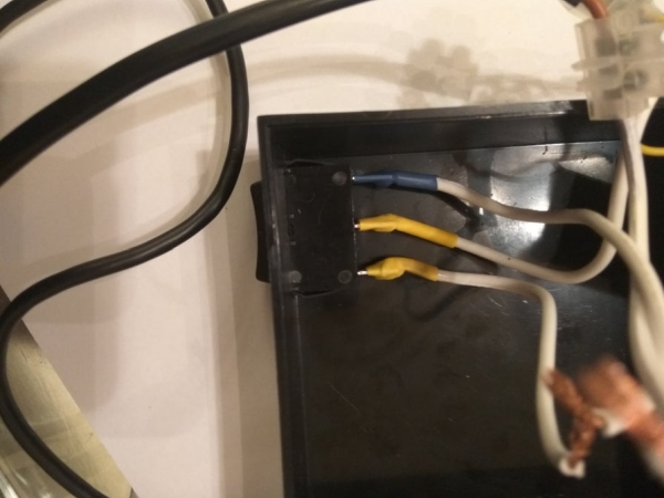
I put the switch on a corner of the box and connected three leads to it. I couldn’t get solder to stick to the pins ,so I twisted the wire, put it through a hole on the pins and used heat shrink tubing to secure the leads.
The power circuit is hot glued on the opposite corner of the switch.
It had started to get a bit crammed so I thought of screwing the relay to the Wemos, to save on cable and space. Thankfully they both had holes for that purpose and they aligned perfectly. I used M3 screws and bolts to secure the relay on the bottom of the board.
I used the cable to connect the charger board to the wemos. I had to bend it a bit to fit. It now provides a bit of “needed” tension on the wemos to keep it in place without glue and also provides easy access to it in case of upgrade.
I also bent the jumper wires at 90 degrees so that I could close the box.
Step 4: The Software
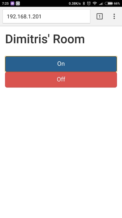
The hardest part was finding something to create the UI. On my first draft I could control the relay using a specific URL eg. 192.168.1.201/gpio/1 or 192.168.1.201/gpio/0 but it was user unfriendly. So I searched around and found the aREST library and the aREST_UI library which creates a simple user interface with an on/off button. The arduino sketch is the following:
/*
This a simple example of the aREST UI Library for the ESP8266. See the README file for more details.
Written in 2014-2016 by Marco Schwartz under a GPL license. *
/ Import required libraries #include #include #include
// Create aREST instance aREST_UI rest = aREST_UI();
// WiFi parameters const char* ssid = “your_ssid”;
const char* password = “your_password”;
IPAddress ip(192,168,1,201);
IPAddress gateway(192,168,1,1);
IPAddress subnet(255,255,255,0);
// The port to listen for incoming TCP connections
define LISTEN_PORT 80
// Create an instance of the server WiFiServer server(LISTEN_PORT);
// Variables to be exposed to the API
int ledControl(String command);
void setup(void) {
// Start Serial Serial.begin(115200);
// Set the title
rest.title(“Dimitris’ Room”);
// Create button to control pin 5
rest.button(5);
// Init variables and expose them to REST API
// Labels
// Function to be exposed
rest.function(“led”, ledControl);
// Give name and ID to device
rest.set_id(“1”); rest.set_name(“esp8266”);
// Connect to WiFi
WiFi.begin(ssid, password);
WiFi.config(ip, gateway, subnet);
while (WiFi.status() != WL_CONNECTED) {
delay(500); Serial.print(“.”);
}
Serial.println(“”);
Serial.println(“WiFi connected”);
// Start the server
server.begin();
Serial.println(“Server started”);
// Print the IP address
Serial.println(WiFi.localIP());
}
void loop() {
// Handle REST calls
WiFiClient client = server.available();
if (!client) {
return;
}
while (!client.available()) {
delay(1);
}
rest.handle(client);
}
int ledControl(String command) {
// Print command
Serial.println(command);
// Get state from command
int state = command.toInt();
digitalWrite(5, state);
return 1; }
What this does is connect to a specific IP address (192.168.1.201), wait for a user to connect and create an aREST object. When the user clicks the ON or OFF button it “flips” the state of pin 5 which is connected to the relay. The pin assignment is not the same on the wemos as the arduino , so you can just poke the pwm pins until the relay “clicks”. On mine, pin 5 corresponds to pin D5 which is also marked D13/SCK.
Just edit the provided sketch with your SSID and Password and the pin you want to use.
Step 5: Issues and Code Update
The first time the board worked for 2-3 hours and then it “lost” its IP (I couldn’t connect to it). Since this is the first revision (!), I hadn’t thought I would need an outside reset switch, so I had to open the box and press the reset manually. Then it worked flawlessly for 2 days and “lost” the IP again. I am thinking of an alternative way to control it just as a fail safe method (eg include bluetooth connectivity). Also the aREST library allows for cloud connectivity, so I could theoretically control it from the web, but I haven’t gotten there yet.
Update:
After it continued to loose it’s IP , I tinkered with the lease time from my router decreasing it from 1440 minutes (1 day), to 5 minutes. That way the situation improved but after a day, it lost it’s IP again. So I tweaked the code a bit. I used the Timer and ESP8266Ping libraries to generate a ping signal to my router every 10 seconds (I know it’s too short, but I’m still testing). If the ESP8266 gets a response ,all is OK, but if the response is missing it uses the ESP.reset() function to restart the wifi server and the connection to the router. The ESP.reset function can be replaced with the ESP.restart() one. The first time I used it and deliberately pinged an “unknown” address (192.168.0.1), the ESP.reset() kicked in ,but the board hanged and I had to manually press the reset switch. After that it worked flawlessly.
Source: Control a Lamp With ESP8266 and a Relay