Introduction
Cooler-Bot is an autonomous vehicle that uses ultrasonic transducers to sense distance and direction to a remote ultrasonic mobile unit that it is designed to follow.
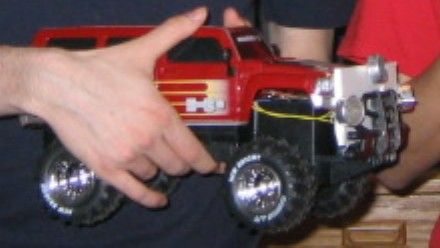
Our original goal was to design a vehicle that would carry a beverages for the user and follow them at a distance of about 1m around the Atmel MEGA16L microcontroller. This vehicle would be ideal for example on a golf course, allowing you to play golf and have a beverage at hand. We decided to use ultrasound for location detection. For the robot, we used a modified, gutted RC car. The car follows a small, remote ultrasonic mobile unit. When the distance to the mobile unit exceeds about 1m, the car will travel in the direction of the mobile unit until the distance is again less than 1m.
Link to Video
High Level Design
Rationale
The idea for this design came when Rob saw a similar device for carrying golf clubs at a golf course. We decided it would be cool to build something like it. We explored several options for distance and location detection. We decided using RF would be far too difficult because the timing is on the order of very short intervals. Infrared was another option, however a large number of sensors would be required. We settled on ultrasound as result.
Background Math
Initially, we planned on using trigonometry to calculate exact position of the mobile unit. However, we later determined that comparing two distance measurements would suffice and simplified the code. Distance from each receiver on the car is approximately equal to the time delay between transmission and reception divided by two, multiplied by the speed of sound:
Distance = (Time)�(Speed of Sound)/2
Logical Structure
Our design process had many stages. First, we tore apart the RC car. We discovered how to power the motors and soldered a board to show motor control. Once the motors were working, we began the task of ultrasonic range finding.
First, we found the resonant frequency of the sensors since there was no datasheet available. We then wrote code to detect and emit short ultrasonic (23.8kHz) pulses. After this, we modified the code to detect distance between an emitter and a receiver. This was then extended to two receivers. We then created a second board that was a simple mobile unit. This board resent any ultrasonic pulses it received, effectively doubling the range. Finally, when all these parts were working, we integrated and tested each system until it worked satisfactorily.
We used the MEGA16L for its A/D capabilities. We chose this over the MEGA32 since we did not need the extra memory. Program details are discussed later.
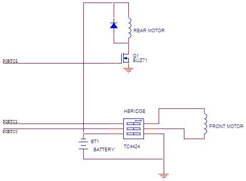
Rear Motor
This motor was controlled via a MOSFET and powered by the car batteries. This motor is used for forward motion.
Front Motor
This motor is controlled through an H-Bridge and again powered by the batteries. This controls turning of the car.
Ultrasonic transducers
These transducers were found in lab. One transducer on the car is used as a pulse transmitter. The transducer on the mobile unit is used to listen for pulses and then immediately retransmit another pulse. The remaining two transducers on the car are used for receiving this retransmitted pulse, thus allowing us to determine distance and direction.
Hardware/Software Tradeoffs
- A/D Sample Rate – We needed to use a high enough sample rate to detect the 23.8kHz signals, so at least 47,600 samples per second were needed. However, sampling too fast reduced accuracy and caused the timer interrupts to not trigger with precise timing. We eventually chose to run the A/D clock at 1/16th the CPU clock, allowing about 71,000 samples per second. In order to keep up with this sample rate, we had to make the detection code efficient. This sample rate offered about 300 cycles to do all conversion math. To optimize this, we only used the high 8 bits of the conversion and did all conversion math outside of the ADC interrupt to allow timer interrupts to trigger on time.
- Tone Detection – We originally were using a tone detector chip to detect 23.8kHz signals. However, the received signals were small (around 100mV) and needed to be amplified to trigger the tone detector. However this caused positive feedback and falsely triggered the detectors often. As a result, we wrote code to detect the tone off the ADC inputs. This code worked well, however it required optimization as discussed above.
- Receiver Positioning – The positions and relative angles of the receivers affected the quality of reception. We experimented with several orientations and eventually decided to put the two receivers about 1 ft apart and angle them about 30 degrees away from center. Also, software thresholds for tone detection were affected by positioning and had to be optimized by trial and error. Too low a threshold allowed false triggering, however too high a threshold reduced range to an unusable amount.
Standards
There are no applicable standards for our project. However, we imagine the noise would annoy several types of animals.
Patents
This type of location is common enough and well known enough that it seems unlikely that there are any active patents regarding our project.
Program and Hardware Design
Program Details
The program on the MEGA16L on the car was used to transmit and detect an ultrasonic pulse, and to control the motors when it was proper. Timer1 and Timer2 were set to overflow at 23.8kHz, and thus OC0 and OC2 produced 23.8kHz square waves. OC2 was switched on and off to power the transmitter, and it was pulsed for a short duration several times a second. OC0 was feed back to an input pin for tone detection.
Tone detection was accomplished using the AD converter in differential mode with 10x gain. Each sample was “multiplied” by the feedback OC0. In reality, the sampled value was multiplied by 1 if OC0 was high, and -1 if OC0 was low. The resulting was low pass filtered by averaging the last 8 samples. This reports a high number if the input is 23.8kHz, but very small input otherwise since:

To determine distance, a timer was run concurrently with the A/D converter. To assure accurate timing, A/D math was done outside of the interrupt to allow the timer to trigger as close to its intended time as possible. The timer had two functions, first to control pulse output and also to then count the time until pulse detection. Each time a pulse was detected by the A/D routine or enough time had elapsed, the A/D input was switched to the other speaker. This way both speakers were sampled and enough time was given for the A/D converter to settle before reading it. Originally, we intended to sample the left and right receivers quickly in succession, however this would not work since the A/D converter needs about 125 microseconds to settle when inputs are switched. This corresponds to minimum observable distance of about 4cm, which was too small for this project. Because we alternated inputs, we could observe both distances by speeding up the pulse rate.
The distance was calculated by averaging the two observed distances. This is not an exact result, but provided enough accuracy for our purposes since the two receivers were relatively close. The rear motors were started whenever the distance exceeded a maximum value experimentally determined to be around a meter. The motors were then stopped if the distance was determined to be less than this value. The motor was pulsed at a 50% duty cycle. This was done because the car’s motor was far too powerful and would often stop but still have enough momentum to attack the user. This resulted in the user running away causing the car to chase them due to positive feedback. We initially intended to calculate angle, however we decided this was unnecessary. We could simply determine rough direction by comparing the distances of the two receivers; for example, if the distance was shorter for the left receiver, this would mean that the user to the left of the car. This provided sufficient accuracy to steer the vehicle.
Parts List:
| Part | Cost ($) | Obtained From |
| RC Car | 20.00 | Toys R’ Us |
| Custom PC Board | 5.00 | Bruce Land |
| Last Year’s Board | 2.00 | Bruce Land |
| 2 MEGA16Ls | 10.00 | Bruce Land |
| 4 Ultrasonic Transducers | 0.00 | Found in Lab |
| 2 BUZ71s | 0.00 | Found in Lab |
| 2 TC4424 H-Bridges | 0.00 | Microchip (sampled) |
| Foam Core Board Piece | 0.00 | Salvaged from Dan |
| 9V Battery Clip | 0.50 | Radio Shack |
| Batteries (1 9V, 4 AA) | 6.00 | Estimated Price, found at home |
| Assorted parts (wires, etc.) | 0.00 | From Lab |
| Total | 43.50 |
For more detail: Cooler-Bot Using Atmel Mega 16L