Introduction
The Cornell University Autonomous Underwater Vehicle team (CUAUV) is an undergraduate engineering team that designs and builds a fully autonomous, robotic submarine. Over the past year, the team – of which both Manoj Lamba and Ian Wang are members – has had a stringent policy of testing the vehicle weekly at Cornell’s Teagle pool. Each session focuses its three hours on testing a few components within the vehicle (e.g. thruster control). When the vehicle experiences a failure that affects the onboard computer, the current logging system is rendered useless. Thus, post “pool test” debugging involves hours of studying the vehicle, attempting to locate the origin of the vehicle failure. Since all components, including the microprocessors, are not only powered by one source but also interconnected, the motivation for designing an independent device that can monitor various nodes in the vehicle, log the data, and be self-powered during the pool test is clear.
The CUAUV Sniffer aims to accomplish the task of independently monitoring and recording data from three types of sensors: voltage sensors (for three nodes), temperature sensor, and light sensor. The Sniffer features a custom-designed printed circuit board with the Atmel MEGA32 microcontroller, serial interface, programmability via an STK500, and the capability of logging from five sensors onto 16 Mb FLASH. The FLASH can be read using a serial client (e.g. Hyperterm).
High Level Design
Rationale and Source of Ideas
As stated before, the rationale of the CUAUV Sniffer is to aid with debugging submarine component failures that end with mi pool testcroprocessor shutdown. Additionally, the device will feed current sensor data to the vehicle’s microprocessor so that members can monitor conditions within the vehicle during a test.
Ideally, a team member could take the Sniffer out of the vehicle, connect it to a computer via RS232 and look at the latest data stored in FLASH for three voltage nodes, the temperature, and the light. Recording voltages in three locations of the vehicle will help in narrowing down where a failure first occurred by looking for spikes in voltages or sharp drops. Noting the temperature will allow the team to determine if overheating is occurring within the submarine’s hull. Lastly, light is used as a sensor so that one knows whether or not the “rack” (the rack secures and fastens all boards to minimize movement within the vehicle) is sealed shut within the hull.
The idea for this project resulted from our own thoughts on what Atmel microcontroller-based project would most benefit the team as well as the advice of a CUAUV electrical leader, Sam Fladung ’08.
Logical Structure
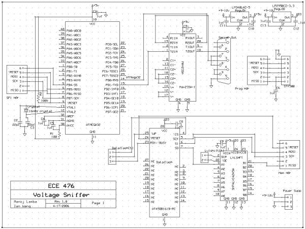
The CUAUV Sniffer sensor board is based around the AVR Atmega32 RISC microcontroller, as shown in Figure 1. This project puts to use the onboard SPI capability for reading and writing to FLASH, UART (or USART) for serial peripheral communication with the vehicle’s processor, and the ADC for converting the sensor signals to bytes for data logging.
The 16Mb Atmel DataFLASH (AT45DB161B-RC ) requires a voltage supply between 2.7V and 3.6V for operation. Thus, the chip cannot use the same supply voltage as that for the Atmega32 (from the 5V regulator). To fix this problem, the Buffer/Level Shifter performs a 3.3V to 5V shift for the SPI signals to and from DataFLASH.
For communication, the ATMega32 and the vehicle’s processor (represented in Figure 1 as “PC (Serial)” must be connected by an RS-232 driver/receiver chip. The Maxim integrated circuit MAX233A accomplishes this task with only one external capacitor required. Other RS-232 driver/receiver chips would require more external hardware, taking up space on an already crowded sensor board. This communication between the processor at the ATMega32 is for determining the state of the Sniffer (please see Figure 7 for the Sniffer State Machine) – if it should continuously log data, to stop logging, or to dump data out for debugging.
The final major component of the CUAUV Sniffer is the sensor array, consisting of five sensors: three to monitor voltage nodes, one for temperature, and one for light. This data is read on a continuous spectrum and must, therefore, be processed in the onboard ADC into one byte (while the ADC can output up to 10 bits, using only 8 will save memory in DataFLASH and still satisfy our requirements for logging the pertinent information. The digital data is then stored in FLASH (by sending over SPI) until it is overwritten or the memory is cleared.
Information transfer and packet protocol, the state machine, and other specifics necessary for understanding the operation of the CUAUV Sniffer will be discussed in the Program/Hardware Design section.
Relationship of Design to Available Standards
The CUAUV Sniffer uses the Recommended Standard 232 (RS-232) for serial binary communication between the PC and the AVR. The implementation of RS-232 used is with a BAUD rate of 9600 Bps, 8 bits, no parity bit, 1 stop bit, and no flow control.
Though not implemented by the due date of this project, the members will continue to add functionality to the CUAUV Sniffer by implementing I2C (inter-integrated circuit) 2-wire bidirectional communication. This standard will allow for extendibility of the monitoring network by allowing additional sensor boards to be added by communicating with each other over I2C.
Existing Patents, Copyrights, and Trademarks
A number of patents were granted for vehicular data logging systems in the early to late 1990s. These logging systems, however, are car-specific, and monitor such events as vehicle speed and vehicle collisions. Thus, the vehicle and types of sensors are different (Two examples of these patents are U.S. Patent #6141610 and U.S. Patent #6795759). Thus, we are not worried about patent or copyright infringement. The logo used for the CUAUV Sniffer project is a derivative of the current CUAUV logo. Though it is not trademarked, we feel comfortable using this logo for a project that will be eventually meshed with the current CUAUV submarine.
If any issues arise with regards to patents, copyrights, or trademarks, we will quickly fix the situation in our constant adherence to the IEEE ethics guidelines.
Program/Hardware Design
CUAUV Sniffer Board Design
The application environment of this project requires a small size with high density of components. The only way to satisfy these two requirements would be to design a custom printed circuit board (PCB) such that, other than the battery, all chips (including the ATMega32, DataFLASH, level shifter, etc.) and sensors would fit on it. In the two-hull SeaMonkey vehicle (the current CUAUV submarine), the CUAUV Sniffer would be placed inside the upper hull, which houses the sensor board, microprocessors, orientation sensors among other parts for operation. To fit in this hull, we set a design requirement for the board to be smaller than 4” by 3”.
For this reason in addition to its low lost, we chose the MiniBoard service through ExpressPCB. These two-layer, double-sided PCBs come in orders of three, each with a dimension of 3.8”x2.5”.
The schematic and layout are both based on Bruce Land’s prototype board for the ATMega32 (see Appendix E). Before designing, we determined that the following components were necessary for building the sensor board:
- ATMega32 Microcontroller
- 16 MHz Crystal
- 5V Regulator
- 16Mb DataFLASH
- Level Shifter (3.3V to 5V)
- MAX233A for RS-232 communication
- RS-232 DB9 Connector
- Holes for sensors, op-amp, resistors, capacitors, headers, wiring, power
(Note: SOICs were the chip preference due to size considerations for this board and future versions of the Sniffer.)
Once these parts were set, and picked out (see Appendix C for manufacturer numbers), we created the schematic and layout using the ExpressPCB software package. Once the design was checked over, it was sent to ExpressPCB to be made.
Upon receiving the board and parts, we soldered all components onto the two-layer board. After testing and debugging the board, the following design errors were discovered:
- The footprint for the MAX233A is for a DIP and not the SOIC (which we are using for size constraints).
- Power was not connected to analog Vcc (AVcc) on the Mega32.
- Ground was not connected to level shifter, one side of the Mega32, and DataFLASH.
- The wrong pinouts were used for the MAX233A (we used DIP pinouts instead of the SOIC.)
- The orientation of power holes on the board is off by 90 degrees.
- The programming header pins are backwards (fixed by putting the header on backside of board).
Such problems were expected with the first version of the CUAUV Sniffer and were temporarily fixed by using rework wiring and an extra SOIC footprint. Version 2 (expected completion date of June 2006) of the CUAUV Sniffer will correct all of these issues.
Temperature Sensor
For monitoring the temperature inside the upper hull of the vehicle, the LM34DZ-ND Temperature Sensor is used. This sensor is picked not only for its range characteristics, but also because the students had used this sensor in Lab 5 of ECE 476.
The non-inverting amplifier (see Figure above) must be constructed to amplify the voltage output of the LM34 Temperature Sensor by a factor of 2. For the circuit, the chosen resistor values are both 10kOhms and the capacitor value is 2nF. The reason for a voltage gain of two is because the accuracy of the A/D converter is +/- the 2 least significant bits. Each bit corresponds to approximately 10 mV while each degree change corresponds to a change in 20 mV. Thus, by amplifying this output, a change in 1 degree will not be considered error and the converter will more accurately represent changes in temperature.
Light Sensor
The photocell (PDV-P9007 ) changes its resistance depending upon the amount of light hitting it. We put the photocell in series with another resistor in the same range as its resistance (10kOhm). As light increases, the resistance of the photocell decreases to as low as 2kOhm. As light decreases, the resistance increases to nearly 200kOhm. Thus, its voltage range swings between 1V and 5V for this application.
Voltage Sensors
As previously stated, there are three voltages sensors on the CUAUV Sniffer board, each performing a different data acquisition.
The first sensor is a 10x magnified differential voltage sensor. This sensor would be useful for monitoring a node that should not experience even small swings in voltage (e.g. monitoring Vcc within the vehicle).
The second sensor is a 1x magnified differential voltage sensor. This sensor would be useful for monitoring any node within the vehicle, not just those that cannot experience small changes in voltage.
The final voltage sensor is a single-ended voltage sensor, with ground connected to the sensor board’s ground. The reason for this implementation of the voltage sensor is because the ADC only allows for two differential sensors.
Power Source
The CUAUV Sniffer must be capable of operating in a mobile environment (the submarine) without using the vehicle’s power source. Thus, the Sniffer uses a 9V alkaline battery because of its low cost and ability to run the sensor board for over two hours. This period of time is well over the required specs for such a logging device.
Operation State Diagram for the CUAUV Sniffer
The state diagram in Figure 2 shows the operation of CUAUV Sniffer depending on the inputs from the microprocessor on the vehicle. The state of the Sniffer begins on “Wait” – it is neither logging data nor sending it. Once the Sniffer is reset by receiving the ASCII byte for `r’ from the microprocessor, it begins continuous logging of the sensor data. It logs one sensor datum each instance TIMER1a overflows. Thus, TIMER1a must overflow five times for data to be obtained from all five sensors. TIMER1a is variable, so that sampling data from the sensors is possible by increasing or decreasing time to overflow.
The microprocessor must send a ping (sending the ASCII byte for `p’) once every five seconds over RS-232 serial to the ATMega32 during the “continuous logging” to remain in the same state. This pinging will hereafter be referred to as the “heartbeat” of the microprocessor on the vehicle, and will be checked after each overflow of TIMER0. After each ping, the ATMega32 returns a real-time message (currently 8-bytes) to the PC (see Packet Structure below).
If the heartbeat is not detected, then the Sniffer will assume a failure has occurred causing the shutdown of the processor. There is no need to continue logging for extended periods of time, as any relevant data that would help with debugging has already been recorded. Thus, the Sniffer moves into the next state, known as the “Timed Logging” state where it records sensor data for an additional five seconds. After this final set of data logging, the Sniffer state switches back to the “Waiting” state. Presumably, the data stored in FLASH has sensor data from before and after the failure, allowing the debuggers to find the problem within the vehicle. Thus, once the Sniffer is removed to the vehicle and connected to another PC over serial, the data from DataFLASH can be dumped out to Hyperterm by sending the ASCII byte `d’ for “Dump.” In its current state, sending `d’ will return a block of data saved in FLASH’s main memory in order to prevent crashing the PC by sending too much information. In order to continue data dumping, the PC must continue to send `d.’
Any state can switch immediately to the “Waiting” state by the PC sending `s’ for “Stop.”
ADC Setup for Multiple Inputs
The analog to digital converter on the CUAUV Sniffer uses five sensor inputs. Since it can only run one conversion at a time, ADMUX chooses which sensor the ADC reads and converts. Thus, the software is written such that ADMUX rotates through each sensor for each TIMER1a overflow.
The most significant 8 bits of data is stored in the ADCH register after conversion by left-aligning the two registers of data. Our requirements allow us to only desire the most significant byte, thus we ignore the lower bits by simply grabbing the ADCH data.
Parts List:
| Part | Cost |
| Atmel Mega32 Microcontroller | $8.00 (rental from ECE 476 lab) |
| STK500 (used only to program the MCU) | Free (borrowed from CUAUV lab) |
| Custom-designed ExpressPCB MiniBoard | $20.00 |
| RS-232 Connector | $1.00 (rental from ECE 476 lab) |
| MAX233A, SOIC | Free (Sampled from Maxim-IC) |
| LM34DZ-ND Temperature Sensor | $2.51 |
| Photocell, PDV-P9007-ND | $1.77 |
| 16Mb DataFLASH, AT45DB161B-RC | $6.02 |
| MP160 16 MHz Crystal | $0.94 |
| Octal Bus Level Shifter, SN74LVC4245A | $0.90 |
| LM340T5 5V Regulator | $1.72 |
| Op-amp, LMC7111 | $1.69 |
| 9V Battery | $2.00 |
| Miscellaneous (wiring, sockets, etc.) | $3.00 |
| Total Cost: | $49.55 |
For more detail: CUAUV Voltage Sniffer Using Atmel Mega32