Introduction
The clock is one of the oldest inventions in human history and has been used for centuries as in instrument for measuring time. There are many ways to implement this ancient technology by simple and practical methods. However, si
mplicity and practicality were not among the goals of this project. Instead, the project is intended to demonstrate an interesting application of available technology, and to create a visually appealing display in the form of a clock. Thus, the final product is more of a novelty item than a practical time-keeping device.
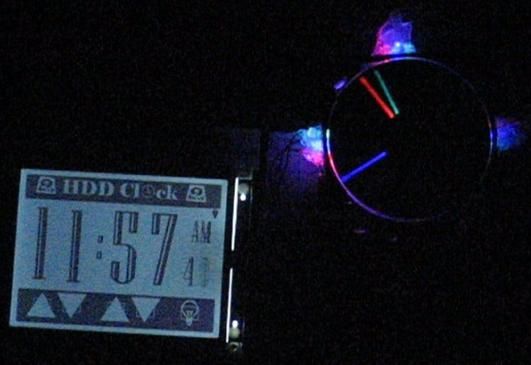
The design consists of two main components: an analog clock created from an old hard drive and some LEDs, and an LCD touchscreen which acts both as a synchronized digital clock and a controller for setting the time.
High Level Design
Rationale and Source of Ideas
There are several reasons why we choose to design the hard drive clock and LCD touchscreen controller for our final project. First, the idea fit well within our budget constraints since the LCD was sampled from www.microtipsusa.com and the hard drive was from an old computer on its way to the junkyard. In addition, the LCD and touchscreen drivers could have many useful applications beyond this project and could easily be incorporated into future work.
The idea of turning an old hard drive into a clock was motivated from a website by Alan Parekh. We wanted to expand and improve upon his concept and it seemed like it would be an interesting example of something the LCD touchscreen could control, as well as a clever way to re-use some old computer hardware.
Logical Structure
A block diagram of the overall system is shown below and a brief description is given for each main component
The LCD touchscreen controller acts as both a digital clock display and a controller to set the time. The LCD is a 320×280 pixel display which contains both a graphical layer and a text layer. The interface is based on the Epson SED1335 controller specifications. The device also includes a touchscreen with a TI ADS7843 controller which interfaces the microcontroller via SPI. The touchscreen is used to create 4 buttons for adjusting the time. An additional button is used to control the LCD backlight setting to one of three modes: always on, always off, or turn on when touched.
The LCD and touchscreen connect to the microcontroller board through a 26 pin cable.
The hard drive clock is created by cutting a slit in the upper platter of the drive. High powered LEDs are placed beneath the spinning platter. In addition, an optical interrupt switch is placed to detect the slit once per revolution. The clock hands can then be displayed by toggling the LEDs at appropriate times based on the slit position. Three different colored LEDs are used: red for the hour hand, green for the minute hand, and blue for the second hand.
Relationship of Design to Available Standards
The only applicable standard to this design is the Hours:Minutes:Seconds standard for displaying time. The relative timekeeping should conform roughly to the Coordinated Universal Time (UTC) standard, although the absolute time may be set by the user.
Existing patents, copyrights, and trademarks
The US patent office granted its first patent for a clock to Eli Terry in 1797, the terms of which have long since expired. In order for a technology to be patentable, it must be considered both useful and non-obvious. Since both clocks and LCD touchscreens are widespread devices, it is unlikely the LCD clock would meet the non-obvious criteria and would therefore not conflict with any current patents. As stated earlier, the idea for the hard drive clock was borrowed from a website by Alan Parekh. However the design and implementation of the idea was our own. To our knowledge there has been no patents granted for this device to either Parekh or another individual.
Program/Hardware Design
MCU board
The Atmel Mega32 microcontroller is housed on the custom prototype board provided for ECE476. Several modifications were made to the board to accommodate our design. First a 26-pin dual row header was added to provide the interface to the LCD touchscreen. A separate 4 pin header connects to the LCD backlight. We also replaced the on-board voltage regulator with a more powerful LM340 5V regulator. This was necessary because the touchscreen LCD required several hundred milliamps of current.
LCD/Touchscreen Hardware
The LCD touchscreen came with an EPSON SED1335 controller for the LCD and a TI ADS7843 controller for the touchscreen connected to a 26 pin connector. Thus, we only needed to provide the connections to these pins. The LCD and touchscreen drivers were implemented in software.
Power Supply
The hard drive is configured with a 4-pin power connection to an ATX power supply. It was convenient to power everything (hard drive motor, LEDs, MCU, and LCD) off this same supply. As with the hard drive, the ATX power supply was taken from an old computer and did not cost anything.
Hard Drive Machining and Construction
We opened the hard drive and removed the read/write arm (including magnetic heads) as well as the voice coil magnets and arm cables. There were five platters but we only need the topmost and bottommost platters. When we removed the middle three platters, we had to account for their height and inserted an extra spacer to keep all the two platters and spacers tight and prevent vibration.
Next, we had to cut a slit 1/8 inch wide in the first platter. We used a dremmel tool with a grinder attachment which cut through the plate without any problems. Next we drilled three holes on each of the three sides of the drive for the LEDs.
The LEDs were mounted in the holes with a skillful use of the glue gun. We soldered the wires directly to the LEDs and ran them to the breadboard. Similarly, the optical slot switch was mounted on the yellow arm stop fixture.
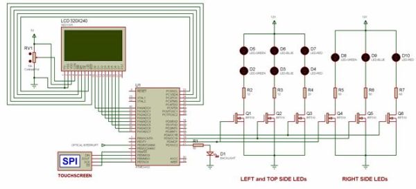
Figure 5: LEDs and optical switch mounted in hard drive
We cut out a white circle of paper and glued it to the bottom plate to reflect and diffuse the light from the LEDs. After everything was complete, we put the top platter back on.
The drive was ready.
Parts List:
| Part | Cost |
| White board | $6 |
| Custom PC board | $5 |
| Mega 32 | $8 |
| LCD touchscreen | $0� Sampled (microtips USA) |
| Old hard drive | $0� Found (old PC) |
| Power MOSFETs | $0� Sampled (fairchild) |
| THC series LEDs (6) | $10.44 ($1.74 each) |
| 5mm LEDs (3) | $1.35 ($0.45 each) |
| Optical Interrupt Switch | $0� Sampled (fairchild) |
| ATX Power Supply | $0� Found (old PC) |
| Total: | $30.79 |
For more detail: HDD analog clock with LCD touchscreen Using Atmel mega32