Introduction
Our final project is a conceptual prototype of a digital receipt system. The basic idea is when making a purchase with a credit or ATM card, the transaction information is automatically packaged and sent to a webserver where it can be logged in a database. A web interface would then allow consumers to log into their accounts and view their transactions online all in one place.
High Level Design
Rationale
The idea for this project came from a course Hain-Lee was taking concurrently with ECE 4760; CS 5150, Software Engineering. One of the potential projects was titled “Paperless World” and entailed developing a software system that would allow for paperless receipts. Consumers would benefit from the convenience of viewing/managing all their receipts online, and retailers would benefit from the additional information about their customers in terms of what they buy, as well as being able to say they are going green by reducing paper consumption. Hain-Lee was really interested in working on that project but unfortunately was not part of the group that was chosen for it. Thus, it became an idea for a final project for ECE 4760.
The idea of paperless receipts (or “digital receipts” or “e-Receipts”) may be new to many consumers, but there are already a couple small companies that have begun setting up such systems. An example is a company called Third Solutions, which runs myreceipts.com (consumer facing) and digitalreceipts.com (for developers and retailers).
For our final project we decided to create a simple conceptual prototype of a digital receipt system, mostly for educational enrichment. This includes interfacing the necessary hardware as well as an elementary web interface to view transactions processed by the hardware.
Logical Structure
The above is a basic block diagram of the hardware connections needed. The keypad and LCD components each occupy one of the four available 8-bit ports on the MCU. Many magnetic stripe readers we found used an RS-232 interface, which only occupies two pins on the MCU. An Ethernet module is required to enable the MCU to send information over the internet.
The general procedure of operating the system is as follows:
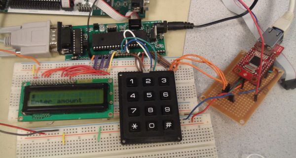
- The “cashier” uses the keypad to enter an amount to be charged, which is displayed on the LCD display.
- After the amount is entered, the “consumer” is prompted to swipe his/her credit card through the stripe reader.
- The MCU receives the decoded data from the stripe reader and parses it to extract the desired data most relevant to the transaction (e.g. the consumer’s first and last name). It also parses the amount entered on the keypad and builds a packet containing all the information pertaining to the current transaction.
- The MCU sends the data to the Ethernet module, which sends the transaction information to a PHP script, and then waits for the response.
- The PHP script takes the data and stores it in a database. A response is sent back to the Ethernet module containing the result (success or failure).
- The Ethernet module receives the response and passes it to the MCU. A confirmation/status message is displayed on the LCD to the consumer, and the process starts again for the next transaction.
This procedure is described and depicted in more detail in the program design section. After a consumer has made a transaction for the first time, an online account is automatically created under the consumer’s name on a website, where the consumer can log in and view his/her transactions. Because the focus of the course is on the microcontroller side, the website/web interface is fairly rudimentary but can be modified and extended with more powerful features and customization independently of the hardware.
[back to contents]
Background Information and Relevant Standards
This section briefly goes over information and existing standards pertaining to magnetic stripe cards and the OSI reference model for network communications.
In a magnetic stripe card for financial transactions, there can be up to three tracks of data encoded. Tracks 1 and 2 are most often used for financial transactions, and track 3 is seldom used. Each track contains different types and amounts of information, but for our project track 1 is most relevant because it contains the cardholder’s name as well as other commonly used information such as card number, expiration date, etc. There are several standards associated with general magnetic stripe cards dictating everything from physical dimensions and sizes of such cards to the location of the various tracks in the stripe (refer to http://en.wikipedia.org/wiki/Magnetic_stripe), but the associated standard specific to financial transaction cards is ISO 7813. The ISO 7813 standard specifies the formats of each of the three tracks. This information was necessary if we wanted to parse data from the card reader on the microcontroller. For more information related to the ISO 7813 standard, refer to the list of References at the end of the report.
On the internet connection side, some knowledge of the OSI reference model is necessary. The model consists of a set of layers that are built on top of each other. The first layer is the physical layer, which defines the physical hardware components and the physical /electrical connections between them. The second layer is the Datalink (often called MAC) layer, and it handles the manipulation of bits and signals to construct logical sequences of units called data frames. The third layer is the network layer, which handles the routing of data through different networks. The layers above the network layer no longer deal with hardware and define protocols and applications for reliability, setting up connections, functionality, and security (refer to http://en.wikipedia.org/wiki/OSI_model). The main idea is that each layer talks only to adjacent layers and can be designed and modified independently of the others as long as the interfaces between each layer remains the same. Each layer has its own associated set of standards and/or protocols. For physical connections, an RJ-45 mag jack is required to plug in an Ethernet cable. The Ethernet standard, associated with the datalink layer, is IEEE 802.3 (Wi-fi is 802.11). The most common protocol in the network layer is IP (internet protocol), which handles naive transfer of data one hop at a time, throwing away packets if errors are detected. Other protocols used in our project and associated with higher layers are TCP (transmission control protocol associated with the transport layer) and HTTP (hypertext transfer protocol associated with the application layer).
[back to contents]
Trademarks and Patents
To the best of our knowledge and searching abilities, the terms “e-Receipts” and “digital receipts” are not registered trademarks (which is why we can title our project as “Digital Receipts”). This project is for educational and demonstration purposes only, and is not at all intended for commercial application (as it is extremely insecure). We will not pursue any patents, as there are already fully featured and developed digital receipt solutions in the market.
[back to contents]
Hardware and Software Design
Hardware Components
ATmega644 MCU + Prototype Board
There was no reason to use a different MCU than we had been using in class already, so we decided to stick with the ATmega644. We also built the prototype board with the custom PCB designed by Professor Land as described here. Because we needed serial communication we included the RS-232 connector on the board as well as a sampled MAX233ACPP chip.
4×3 Keypad
The keypad we used has buttons for digits 0-9, * and #. The lab already had 4×4 keypads, but we chose a 3×4 keypad because of cost (we were able to find a significantly cheaper 3×4 keypad). The keypad is matrix encoded and thus only occupies 7 pins of the MCU. Furthermore, the keypad scanning routine used in previous labs for 4×4 keypads could easily be adapted for the 3×4 keypad. Although a 4×4 keypad contains more buttons that can be used for additional functions, we can compensate by encoding simultaneous button presses on the 3×4 keypad.
16×2 LCD
The LCD display included the standard HD44780 controller and occupied 7 pins of the MCU. Because it uses the same interface as in previous labs, the same LCD library could be used to drive it as well.
Magnetic Card Reader
On a credit card magnetic stripe, the cardholder’s name is stored only on track 1. Therefore, we needed to obtain a magnetic card reader that could read track 1. The card reader includes its own controller that can read the data from a magnetic stripe and send the decoded information over the serial interface. The serial interface occupies 2 pins on the MCU.
Ethernet Module

Because the card reader occupied the RS-232 UART on the microcontroller, we needed an Ethernet module that could communicate using a different interface. There were some Ethernet modules that supported a direct 8-bit interface, but this was not feasible because of the limited number of available pins. For this reason SPI was ideal because it only requires 4 pins on the MCU. The need for an SPI Ethernet module ruled out using a Lantronix module. Wiznet, on the other hand, manufactures a number of Ethernet modules that can communicate using SPI. The module we ended up using for the project is a Wiznet WIZ812MJ, which uses the Wiznet W5100 chip.
Parts List:
| Item | Cost | Source |
|---|---|---|
| Custom PCB for MCU | $4.00 | 4760 Lab |
| MAX233ACPP | sampled | Maxim IC |
| ATmega644 | sampled | Atmel |
| 40-pin DIP socket | $0.50 | 4760 Lab |
| 20-pin DIP socket | $0.50 | 4760 Lab |
| Male headers for custom board | $1.65 | 4760 Lab |
| 12V Power supply | – | previously owned |
| 3.3V lab supply | $5.00 | 4760 Lab |
| RS-232 Connector | $1.00 | 4760 Lab |
| 4×3 Keypad (KEYPADSM) | $2.20 | Futurlec |
| Female headers for keypad | $0.70 | 4760 Lab |
| Male headers for LCD | $0.70 | 4760 Lab |
| Female headers for LCD | $0.70 | 4760 Lab |
| Powertip 16×2 LCD (PC1602LRU-FSO-B) | $3.00 | Bonanzle.com |
| Ethernet Module (WIZ812MJ) | $15.99 | WIZnet |
| Small Protoboard | $1.00 | 4760 Lab |
| Female headers for ethernet module | $0.35 | 4760 Lab |
| Magtek Mini Swipe Reader (21040071) | $34.90 | POSSavings.com |
| RS-232 null modem cable | free | 4760 lab |
| 6 inch prototype board | $2.50 | 4760 lab |
| Total Cost | $74.69 |
For more detail: Digital Receipts System Using Atmega644