Summary of DIY Atmel Microcontroller Development Board
This Instructable shows how to build a compact Atmel microcontroller development board (used with DIP-package MCUs) that saves breadboard space and provides a single connector for programming. The project uses two female 40-pin headers, a 10-pin programmer header, a small protoboard, an LED with resistor, an Atmel MCU (ATmega32A in the example), and a USBasp programmer, with solder bridges to route power and programming signals.
Parts used in the Atmel Microcontroller Development Board:
- Two 40 pin female header strip
- 10 pin male header (programmer connector)
- 40 pin male header strip (optional mentioned)
- 5x7 cm point-to-point circuit board
- 3 mm or 5 mm LED
- 330 Ohm resistor
- Atmel microcontroller (example ATmega32A)
- USBasp USB programmer
In this Instructables I am going to show you how to make a very useful development board for your favourite Atmel microcontroller that will help you save up to the third of the space on your breadboard and let you move your microcontroller around without any loose connections problems. It will also help you connect your programmer easily without the need of connecting all the cables individually with jumper wires every time, Only one simple connection will be needed and you’ll be ready to program it.
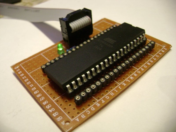
I used an ATmega32A but this can be done with almost any Atmel microcontrollers (Through holes DIP pins one only) .
Step 1: Gather the Parts Needed.
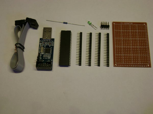
Here’s what you’ll need:
- Two 40 pin female header strip ($1.31 CA/$1.03 US for 3 pcs)
- One 10 pin male header that has the same pinout than the programmer’s connector that are very common on Computer motherboards and scrap circuit boards or it can be done with a male header strip 40 pin male header strip ($1.06 CA/$0.99 US for 10 pcs)
- One 5x7cm point-to-point circuit board ($1.84 CA/$1.45 US for 10 pcs)
- One 3 or 5mm LED (who doesn’t have LED’s???)
- One 330 Ohm resistor
- One Atmel microcontroller of your choice, I used the ATmega32A 8bit AVR microcontroller that I bought on ebay for only $3.02 CA/$2.38 US 🙂 ATmega32A Microcontroller
- One USB programmer, I used a super cheap USBasp programmer for only $2.60 CA/$2.05 US. USBasp Programmer
That’s all! ^^
NOTE: all the links are from ebay sellers from china and it can take up to over a month before you receive your items.
Step 2: Solder the Famale Headers Strip to the Circuit Board
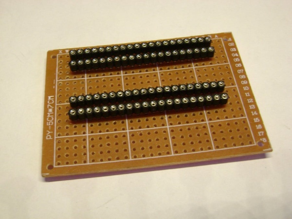
Break the female header strips at the same length than your microcontroller and place them on your circuit board making sure that the spacing is the same than your microcontroller.
Then, solder them at their end making sure they are strait. Now that they are holding in place solder all the pins to the circuit board.
Step 3: Bridge the Headers Together
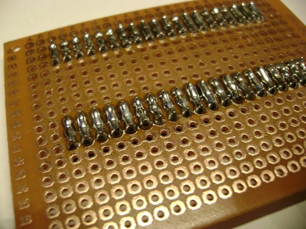
Bridge the headers together with solder making sure you don’t short any connections.
Step 4: Install the 10 Pin Programmer Male Header and Power LED
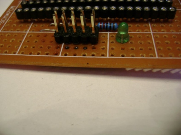
Solder the 10 pin male header to the circuit board and connect it to the microcontroller female header with solder bridges and wires following the datasheet of your microcontroller.
Connect the power indicator LED cathode (-) to GND (5V-) and the anode (+) to one end of the 330 Ohm resistor and connect the other end of the resistor to VCC (5V+).
Now you’re ready to test it to make sure everything is working.
Step 5: Test It!
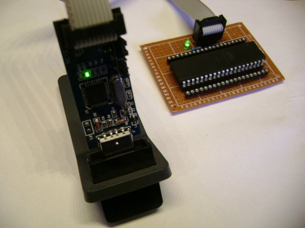
First of all before plugging it for the first time, check all your connection making sure they are all connected at the right place and that nothing is shorting out.
Make sure that the jumper on the programmer is selecting the right voltage for your microcontroller (3.3V or 5V).
Plug the USBasp programmer into a USB port of your programmer and test… The LED on the programmer and your development board should turn on, without everything burning into smoke!
Setting up the Cheap USBasp to work with Atmel studio isn’t easy so if you want, request an Instructables on how to set it up and I’ll gladly do it for you guys. 🙂
Source: DIY Atmel Microcontroller Development Board
- Can this board be used with microcontrollers other than the ATmega32A?
Yes, it can be done with almost any Atmel microcontroller as long as it is a through-hole DIP package. - What headers are used to hold the microcontroller?
Two 40 pin female header strips are used, cut to the microcontroller length and soldered to the protoboard. - How is the programmer connected to the board?
A 10 pin male header is soldered to the board and bridged by solder and wires to the microcontroller pins following the MCU datasheet. - How is the power indicator implemented?
An LED is connected with its cathode to GND and its anode through a 330 Ohm resistor to VCC. - What should be checked before the first power-up?
Check all connections for correct placement and ensure there are no shorts. - Does the USBasp require configuration for Atmel Studio?
Yes, the article notes setting up the USBasp for Atmel Studio is not easy and offers a separate guide on request. - What voltage considerations are there for programming?
Make sure the programmer jumper selects the correct target voltage (3.3V or 5V) for the microcontroller. - Are solder bridges used in this build?
Yes, solder bridges are used to connect header pins and to route signals between the programmer header and the microcontroller headers.