Summary of Drawing geometric figures on a PAL TV using ATmega32 (128×64 resolution)
This hobby project uses an ATmega32 microcontroller to draw geometric shapes like lines and circles on a TV screen. The author implements a 128x64 pixel resolution by managing a digital display buffer (paper) with "pencil" and "eraser" functions to set or clear pixels. The system relies on timer interrupts generated every 64 microseconds, driven by a 16.450MHz external crystal, to handle raster scanning and update the screen buffer effectively.
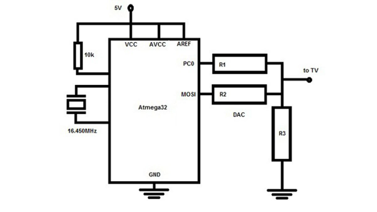
Parts used in the Drawing on TV Screen Project:
- ATmega32 Microcontroller
- TV Screen
- 16.450MHz External Crystal
- Timer Interrupts
- Display Buffer (disp_buffer)
Introduction:
I am interested to draw lines, square, rectangle, circle etc on my TV screen. At first I was confused where to start. While thinking about it, a pencil and an eraser came to my mind. If we have a good pencil, eraser and a paper, then we can draw on it according to our own logic. If we use the pencil with compass and scale, we can draw circle, line, box etc on the paper. This is the basic idea I implemented in this small hobby project.
I divided my tv screen into 128 x 64 pixels. I am using atmega32 microcontroller. It got 2kb RAM. So, if each pixel takes 1 bit, then 128 x 64 pixels takes (128*64/8) = 1024bits of RAM(screen buffer). Still I can increase the resolution but any way at present I am satisfied with this because it is my first attempt and I can improve it later.
Here a horizontal line in TV(two lines) takes 16byte, ie horizontal resolution now is 16*8 = 128 pixel. Similar 64 bytes are stacked up and thus the vertical resolution now is 64 lines. I am using fake interlacing so total vertical lines are 312 and here again I combine 2 lines to a single line which takes 1 16byte row of the screen buffer.
I told about a pencil at the starting of the post, that is nothing but a function which could set a pixel. The eraser is a function which clear a pixel. Now the paper is the a digital display of 128×64 pixels, the smallest dot is 1 pixel.
- What microcontroller is used in this project?
The project uses an atmega32 microcontroller which has 2kb RAM. - How is the TV screen resolution defined?
The screen is divided into 128 x 64 pixels using a character array of 64 rows and 16 columns. - What function acts as the pencil for drawing?
The setpixel(x,y) function serves as the pencil to set a pixel. - What function acts as the eraser?
The clrpixel(x,y) function serves as the eraser to clear a pixel. - What clock frequency is used for timer interrupts?
An external crystal of 16.450MHz is used to generate precise timer interrupts. - How often are timer interrupts generated?
Timer interrupts are generated every 64 microseconds for raster scanning. - Does the project support interlacing?
Yes, the project uses fake interlacing where total vertical lines are 312 and two lines are combined. - What is the purpose of the disp_buffer array?
The disp_buffer stores pixel information for the 128x64 screen to allow drawing pictures.