This article describes a DIY OLED alarm clock project using an Arduino Micro, DS3231 RTC module, and 128x64 SSD1306 display. It features two versions (digital/analog and Pusheen graphics), an I2C menu system for setting time/alarm without USB, and an updated alarm function with improved seconds accuracy.
Parts used in the OLED Alarm Clock:
- Arduino Micro
- SSD1306 controller 128x64 OLED display
- DS3231 real-time clock module with rechargeable battery backup
- Two SPST normally open push buttons
- Piezo 5 volt buzzer/beeper
- Adafruit graphics libraries
- DS3231 library
UPDATE: I updated the code so that setting the clock does not affect the seconds accuracy – no resyncing of seconds required.
UPDATE: I removed the personal messages from the clock code for the “Pusheen” version in the download links
Video at:: http://youtu.be/ikNw1iLE9vg
Alarm demo video: http://youtu.be/jlZBCuQeswA
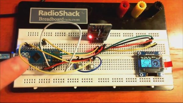
This is an OLED alarm clock I built using an Arduino Micro, a tiny OLED 128×64 display using the SSD1306 controller and I2C interface, and a precision DS3231-based real-time clock module with rechargeable battery backup. It features a menu system for setting the RTC (no serial port or USB required)
Two versions are shown – the basic digital/analog clock and a version with “Pusheen” graphics and animation.
It uses the Adafruit graphics libraries and DS3231 library, included in the distribution.
Code for both, including needed libraries, at http://projectmf.homelinux.com/Arduino/ – or download directly from the link below in Step 4.
Step 1: Connect the DS3231 module and 128×64 OLED module to the Arduino
- Connect ground connection from Arduino to the DS3231 RTC module and OLED display.
- Connect +5v from the Arduino to the +5v connections on the DS3231 RTC module and OLED display.
- Connect the pin assigned to the SCL function on your Arduino to the SCL pins on both the DS3231 module and the OLED display.
- Connect the pin assigned to the SDA function on your Arduino to the SDA pins on both the DS3231 module and the OLED display.
- Connect one side of two SPST normally open push buttons to an Arduino ground connection.
- Connect the other side of one push button to pin 8 of the Arduino. This is the time/date/alarm set mode select button.
- Connect the other side of the other push button to pin 9 of the Arduino. This is the time/date/alarm set change button.
- Connect the black wire on a piezo 5 volt buzzer/beeper to the Arduino ground connection. Connect the red wire from the piezo buzzer/beeper to pin 10 of the Arduino. Be sure to use a piezo beeper (NOT a piezo speaker) that generates its own tone when 5 volts is applied. If you use a piezo speaker instead of a piezo beeper, it will only click rapidly when the alarm is triggered. A unit that sounds continuously when power is applied is best, as the code generates a 5Hz interrupted voltage source to pin 10 on its own.
- Download either the regular or “Pusheen” version of the clock code from here or the link in the introduction.
- Install the Arduino libraries in the software distribution .zip file.
- Compile and download the code to your Arduino. The clock and display will start to run.
- Set the clock and alarm per the instructions in the next step.
For more detail: DS3231 OLED alarm clock with 2-button menu setting and temperature display
-
How do I connect the SCL and SDA pins?
Connect the pin assigned to the SCL function on your Arduino to the SCL pins on both the DS3231 module and the OLED display, and connect the pin assigned to the SDA function on your Arduino to the SDA pins on both modules. -
Can I use a piezo speaker instead of a piezo beeper?
No, you must use a piezo beeper that generates its own tone when 5 volts is applied because a piezo speaker will only click rapidly when the alarm is triggered. -
Which Arduino pins are used for the push buttons?
One push button connects to pin 8 for mode selection and the other connects to pin 9 for changing time, date, or alarm values. -
Does setting the clock affect seconds accuracy?
No, the code was updated so that setting the clock does not affect the seconds accuracy and no resyncing of seconds is required. -
Do I need a serial port or USB to set the clock?
No, the device features a menu system for setting the RTC that requires no serial port or USB connection. -
What voltage powers the piezo buzzer?
The piezo buzzer operates at 5 volts, with the black wire connected to ground and the red wire connected to pin 10 of the Arduino.