Introduction
Our project is a self-contained system that helps people develop the musical skills of perfect pitch and relative pitch. Push buttons allow the user to navigate a graphical user interface (GUI) on a liquid crystal display (LCD). In perfect pitch training mode, a note is played and the user tries to identify the note on an animated keyboard. In relative pitch training mode, an interval is played, and the user selects the correct interval name from a list of possible intervals. A musical instrument digital interface (MIDI) input is implemented so users can simply press a key on a MIDI keyboard instead of navigating the animated one. Musical notes are generated using direct digital synthesis (DDS).
High Level Design top
Rational
I played piano growing up and I was always envious of those who can play by ear or transpose music on the spot. Then I learned the concepts of “perfect pitch” and “relative pitch.” Perfect pitch is the ability to identify musical notes without an external reference and relative pitch is the ability to hear the interval between notes. Perfect pitch allows musicians to play by ear and relative pitch allows musicians to transpose musical pieces. They are separate abilities that can be trained contrary to popular belief. To train myself, I often sit next to a piano and test myself. The drawback is that I need a piano and that even while not looking at the keys, the position of my hand often give the notes away. Then I thought to myself, wouldn’t it be nice to be able to train myself without a piano? Our project “Ear Trainer” develop one’s perfect and relative pitch by generating random note(s) for users to identify the note(s) or the interval using an Atmel ATmega644 microcontroller (MCU). For users that want to answer using a piano, we allowed a MIDI input into the microcontroller.
Our project consists of two sources of input that control two outputs. The software is governed by a state machine that controls DDS and the LCD. The inputs are push buttons that are debounced by the state machine to control the GUI on the LCD and a MIDI input so that a user can hook up a keyboard. The MIDI is interfaced to the MCU via the universal asynchronous receiver/transmitter (UART). The MCU communicates with the LCD via serial peripheral interface (SPI). The direct digital synthesis creates a pulse width modulated (PWM) waveform that is filtered to create the sinusoidal waveforms for the speakers.
Standards
We use the ISO standard for the frequencies of our musical notes. We also adhere to the IEEE Code of Ethics.
Background
Direct Digital Synthesis
To generate musical notes from the microcontroller (MCU), we use direct digital synthesis (DDS). The duty cycle of a pulse width modulated (PWM) signal is changed according to a table of sine values. The frequency of the sine wave is controlled by how quickly one iterates through the sine table. A low pass filter acts as an averager, converting the digital signal into an analog one that can be played by a speaker. Multiple notes can be generated at once by summing sine waves.
MIDI
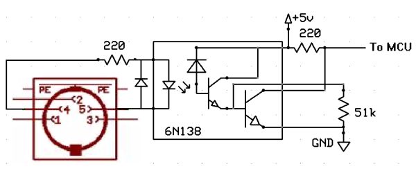
MIDI is a protocol that allows asynchronous serial communication between electronic musical instruments and computers. Data is transmitted serially using event messages that contain information about pitch, intensity, and other parameters. Event messages consist of at least two bytes. The first byte is always a status byte that inform the receiver how to interpret subsequent bytes. In our case, we are only interested in the NOTE_ON status, which is sent when the user presses a key. When that status is detected, we can determine which key was pressed from the rest of the message. The baud rate is 31,250 bits per second, with a start bit, a stop bit, and no parity bits.
Musical Note Frequencies
| Note | Freq. (Hz) |
| C4 | 261.63 |
| C#4/Db4 | 277.18 |
| D4 | 293.66 |
| D#4/Eb4 | 311.13 |
| E4 | 329.63 |
| F4 | 349.23 |
| F#4/Gb4 | 369.99 |
| G4 | 392.00 |
| G#4/Ab4 | 415.30 |
| A4 | 440.00 |
| A#4/Bb4 | 466.16 |
| B4 | 493.88 |
Serial Peripheral Interface
Serial Peripheral Interface (SPI) is a synchronous serial data transfer scheme for communication between a master device and a slave device. The SPI bus consists of four lines. The serial clock (SCLK) line is a clock signal provided by the master device to keep things synchornized. The master out slave in (MISO) line carries data that is transferred from master device to slave device. The master in slave out (MOSI) lines carries data that is transferred from slave device to master device. The chip select (CS) line selects the slave device to which the master device is sending or receiving data.
Hardware/Software Tradeoff
First, we had to pick a LCD display. The LCD used in previous labs could only display 2 lines of 16 characters each, which was not enough for our needs. One of our friends had a Playstation Portable screen that we could use, but after looking into it, we concluded that a more powerful MCU was needed to run it, especially with our plans to run direct digital synthesis and take in MIDI input. We settled on a color LCD that is a knockoff of a Nokia cell phone screen. The screen resolution and the cost were both satisfactory.
DDS accumulator
We sacrificed some precision with direct digital synthesis (DDS) because we wanted to generate three notes at once. The 32-bit accumulators used in the DTMF dialer lab work for generating two notes simultaneously, but they take a relatively long time to perform addition and shift operations. We ran into trouble when we tried to generate three notes, so we changed the accumulators to be 16-bit. The frequencies generated were still close to the desired frequencies.
We considered whether to use a keypad or make our own input interface with push buttons. Both could have worked. The buttons on the keypad would have needed to represent things other than the keys 0-9 and A-D. Once we decided that we were going to draw a keyboard on the LCD, it made more sense to make our own push button interface with four arrow keys and an enter key. We thing moving around the keyboard with arrows is more intuitive than pressing alphanumeric keys on a keypad.
ATMega644
We used a custom printed circuit board designed by Bruce Land and Nathan Chun for the ATMega644. We did not solder on the parts necessary for RS-232 communication due to cost constraints. We ended up soldering a different switch on a solder board to allow users to turn our project on and off without having to open the packaging. We also added a voltage regulator after the switch to provide current for the backlight since the regulator on the board is not rated for the amount of current we needed. Protoboard
LCD
We used a color LCD that is a knock-off of a Nokia cell phone LCD. The screen is 132×132 pixels on an area of about 3.5×3.5cm. It is capable of displaying up to 16-bit color, but we decided to use 12-bit color because it requires less data transfer and we only use a few colors. We chose this LCD because it is a cheap color LCD with good enough resolution for our purposes. The availability of a breakout board and the fact that many people have interfaced to it with MCUs before were also a plus.
The LCD has a controller chip that holds the information for each pixel. We communicate with the controller via SPI. The SPI is not a normal 8-bit SPI, but rather a 9-bit SPI, so could not use the built in SPI on the MCU. The extra bit is used to signify whether a transmitted byte is a command or data. The LCD controller only receives data, so we did not need a MISO line. We successfully run the SPI at 16MHz even though the datasheet for the controller says the period of the serial clock should not be less than 150ns, which corresponds to operating at around 6MHz.
The LCD controller operates at 3.3V, so we could not directly hook it up to the MCU. We used a buffer as a level shifter for our SPI lines. By providing 3.3V to the VCC of the buffer chip, the maximum output of the buffer is limited to 3.3V, which is acceptable for the LCD controller.
Parts List:
| Item | Source | Quantity | Cost |
| Solder Board | Lab | 1 | $2.50 |
| Small Solder Board | Lab | 2 | $2.00 |
| Power Supply | Lab | 1 | $5.00 |
| Custom PC Board | Lab | 1 | $4.00 |
| Mega644 | Lab | 1 | $8.00 |
| Header plugs | Lab | 36 | $1.80 |
| Headers | Lab | 8 | $8.00 |
| LCD Breakout Board (Sparkfun: LCD-08600) | Sparkfun | 1 | $34.95 |
| CD74HC4050E Level Shifter (Digikey: 296-9213-5-ND) | Digikey | 1 | $0.52 |
| LD1117V33 Voltage Regulator (Digikey: 497-1491-5-ND) | Digikey | 1 | $0.68 |
| LD1117V50 Voltage Regulator (Digikey: 497-7311-5-ND) | Digikey | 1 | $0.65 |
| 40-pin DIP socket | Lab | 1 | $0.50 |
| MIDI Connector (Sparkfun: PRT-09536) | Sparkfun | 1 | $1.95 |
| MIDI Cable | Own it | 1 | – |
| Box | Own it | 1 | – |
| Resistors, Capacitors, Wires, Audio Connector, Push Buttons, Heat Sink, Diodes, Switch | Lab | – | – |
Total: $70.55
For more detail: Ear Trainer Using Atmega644