For our ECE4760 final design project, we designed and built a two player game system for rock-paper-scissors. Our implementation involved the use of two sensor gloves (one for each player) that tracked bends in the user’s fingers, to determine the symbol put out by each player, as well as hand acceleration, to track the start and end of each game.

The game system connected to a computer through the use of a USB serial connection to print game data and game statistics to the computer screen. An additional feature was implemented to ensure that both players displayed their symbols at the same time and kept the same pace to prevent cheating.
High Level Design
Game Rules
Rock-paper-scissors is a game typically played with 2 players in which each player must display either the symbol for rock, paper, or scissors. The following list describes the hand positions for each symbol:
- Rock: represented by making a fist
- Paper: represented by an open hand, with the fingers kept together
- Scissors: represented by extending and separating only the index and middle fingers
To begin a game of rock-paper-scissors, both players make a fist with one hand and hit it against their other hand which is open with the palm facing up (hand hit). After the players have completed three hand hits together, they each display one of the three symbols. The following rules are then used to determine the winner:
- Rock defeats Scissors
- Scissors defeats Paper
- Paper defeats Rock
Rationale
The idea of exploring new ways to interact with computerized systems led us to the idea of designing some kind of device that would be able to use human motion as an input. Since the hands and hand gestures often serve as a means of communication and emphasis, we believed that implementing a sensor glove would be an interesting way to capture human motion and to control a system. The rock-paper-scissors game provided us with the opportunity to capture several aspects of hand motion including finger bends and hand acceleration in an interactive system.
Our original interest in hand movement tracking and sensor gloves stemmed from a description given in lecture of a previous year’s project that dealt with using hand gestures and movements to control a computer. We immediately began thinking of different applications of sensor gloves as well as interesting and fun ways to demonstrate their functionality. After much thought, we eventually landed on the rock-paper-scissors game.
When going through the list of previous year’s projects, we discovered that another group had implemented their own version of rock-paper-scissors that used CMOS cameras to determine the symbol put out by the player. While both projects had the same end goal, our method of actively tracking finger bends with acceleration with hand sensors was significantly different then their method of capturing an image of the player’s hand. In addition, our system also focused on the interaction between two human players which introduced issues of timing between the two player’s symbol displays to keep the game fair and ensure all game rules were followed. As such, we believed our project was significantly different from any previous project and was a worthwhile pursuit.
Logical Structure
Our project was structured so that the two sensor gloves were completely independent of each other and interchangeable. As such, the hardware for each glove was kept separate from the other. We found this organization to be extremely important as it allowed for easy tracking of hardware problems to a specific glove as well as simpler circuit layout, construction, and system setup. Each glove consisted of an accelerometer and two finger flex sensors directly attached to the glove as well as three comparators on the base unit which served as analog to digital converters for each of these components. Thus, each glove required three connections to the microcontroller to send the hand motion data for analysis. Each glove was set up to attach to a different port on the Mega644 microcontroller as each glove required the use of an external interrupt to count the hand hits (the motion required to start the game). In addition, this also helped when setting up the system for use as the sensor input pins for each player were on different ends of the prototype board.
The signals from the two gloves were interpreted and analyzed in software. The microcontroller’s hardware timer0 was used to count milliseconds to serve as a reference time for the system. All timing constraints and scheduling used software timers based off of the millisecond count of timer0. The ISR for each accelerometer was triggered on each hand hit and set up to track the number of times each player performed that motion (3 were required by each player before the symbols were determined). The finger flex sensor signals were read off the microcontroller ports after the system had detected the starting sequence of three hand hits. The code was then responsible for determining the winner and sending the results via serial connection to the computer to be printed in PuTTY.
Hardware/Software Tradeoff
Originally, we had decided to purchase variable resistive flex sensors in order to track the finger positions of each player. However, due to the high price, we could not afford to put five flex sensors into each sensor glove. As such, we determined that at a minimum, we needed only two flex sensors, one for the index finger and one for the ring finger. By tracking just those fingers, we could detect any of the three symbols involved in the game, assuming the user actually displays one of the real symbols. Since the system does not track the thumb, middle, or pinky fingers, the system may detect a legal symbol when the user does not actually display one. In the end, we decided not to purchase the resistive flex sensors but to make our own. We still decided, however, to stick with using only two flex sensors per hand in order to simplify the design. Using a smaller number of sensors allows for easy repair and replacement of the flex sensors. This, in turn, also simplified the software symbol detection engine as only two fingers had to be analyzed to determine the symbol displayed by each player
During the planning stages of the project, we realized that the sensor components that we wanted to use in the sensor glove all contained analog outputs. As such, we needed a way to convert all the sensor output signals into digital signals that could be used by the microcontroller. Since each glove consisted of two flex sensors and an accelerometer, we needed 6 total (3 for each glove) analog to digital converters. However, the Mega644 only contains one dedicated analog to digital converter. Instead of using the built-in ADC, we instead had to build 6 external ADCs using op amp comparators.
We could have used the microcontroller’s internal ADC to read the flex sensor signals. However, it would have been more difficult to have an adjustable threshold voltage when the device was in use outside of the lab environment. As such, we decided to implement the comparison in external hardware.
Standards
Our game implementation required a serial connection via RS232 in order to print game data to the computer. The provided UART library and code from the course website handled all issues related to this standard.
Patents, Copyrights, Trademarks
Microsoft Corporation holds a patent on a type of gesture detection system. In the patent description, a rock paper scissors game is described. However, their detection system is different from ours because their system uses gesture input from an optical and touch sensitive device, while ours uses a glove with flex sensors. This patent can be reviewed here.
To the best of our knowledge, there are no other directly relevant patents, copyrights, or trademarks related to our implementation of our rock-paper-scissors game or sensor gloves.
Software
Program Description
The program portion of the project was divided up into three main stages: (1) preparing the system for game play, (2) detecting the starting sequence of hand hits, and (3) reading the players’ symbols and determining the winner.
1. Preparing the system for game play
The preparation stage of the program was responsible for initializing all of the software timers and game variables. The initialization statements involved in this portion of the code were all grouped together in a function called resetGame() which would be called the first time the system was turned on as well as after each round of the game. The organization into a single reset function allowed for better organization of the code and was very convenient as the reset function is called in multiple places throughout the code. The game variables that kept track of the total number of wins for each player were not in this reset function as we wanted to preserve these values for the entire time the system was on.
The system setup stage also involved setting up hardware timer0. In the program, timer0 was used to create a 1 millisecond timer which served as the source to all of the software timers in the program. As such, timer0 was set up with a prescalar to divide by 64 and to trigger an ISR and clear when its count reached 249 (corresponding to 1 millisecond). The timer0 compare match ISR was used to update all software timers that were currently operating. These timers will be discussed in the subsequent sections.
Finally, the preparation code set up two external interrupts, one on int0 and the other on int2, for the detection of the starting sequence and initialized the UART. The UART was used for printing the results for each game to PuTTY on the computer.
2. Detecting the starting sequence of hand hits
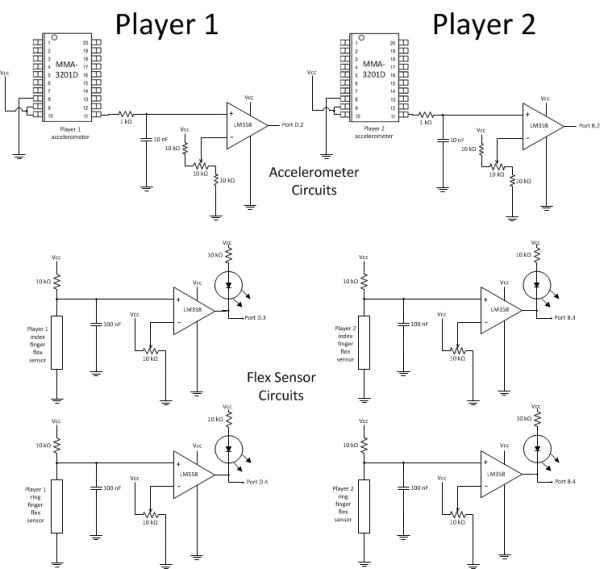
The accelerometer from each player’s glove was connected to a comparator which returned +5V when the glove was hit against the hand for the starting sequence and 0V otherwise. The output from player 1’s comparator was connected to external interrupt int0 (pin D.2) and the output from player 2’s was connected to external interrupt int2 (pin B.2). Both external interrupts were set to trigger on the rising edge. As such, an ISR was triggered whenever a player completed a hand hit.
Before the symbols could be evaluated for each player, each player needed to have completed three hand hits. There were several rules that dictated how the players could increase their hand hit counts in order to complete the game:
- No player’s count can be more than 1 greater than the other’s. This was to prevent one player from getting too far ahead of the other.
- No player’s count can be greater than the other’s for 400 milliseconds otherwise the game will timeout. This was to ensure the game was fair by making sure that the player’s were on approximately on the same playing pace. This also prevented a player from waiting to see the other player’s symbol before completing their set of hand hits and displaying their symbol.
- No player can increment his count within 50 milliseconds of a previous increment. This was to prevent any double triggering caused by the accelerometer.
- No player’s count can be greater than 3. Since only three hand hits are required for each game, there is no reason to count any higher.
Each time a player’s hand hit ISR was triggered, a variable holding their total number of hand hits in the current game was increment unless one of the above rules was violated.
After each registered hand hit for each player, a 50 millisecond timer would be started. During this 50 millisecond period following a player’s hand hit, that player would not be able to register another hand hit. This timer prevented multiple triggerings of the accelerometer comparator on one hand hit from registering multiple times. Since this time was small compared to human hand movement speed, it would most likely not be noticed by the players. This timer was controlled in the timer 0 compare match ISR which was run every millisecond. Whenever the timer count was greater than 0, it would be decremented every millisecond. Once the timer had reached 0, the hand hit could be incremented once again. To start the timer again, the timer count variable would simply be reset back to 50.
A variable was used to track when the hand hit counts of the players were equal (evenCount). This variable would indicate when one player was ahead of the other in the game. In addition, on the first hand hit (by either player), a flag variable was set to indicate that the game had started. When the counts were not equal, the 400 millisecond game timeout timer was started. If the counts were not even after 400 milliseconds, the game would end. When the counts were even, the timer would be reset. The timeout timer was controlled in the timer0 compare match ISR which was run every millisecond. If the game started flag was set and the count was marked as being uneven, the timeout timer variable would be decremented. Once this timer reached 0, a flag would be set to indicate that the game should be ended with no winner and the timer would be reset for the next game. After this flag had been set, the reset function would be called and the flag variable reset in preparation for the next game. A timeout error would also be printed to PuTTY.
3. Reading the players’ symbols and determining the winner
After both players had reached a hand hit count of 3, the system could proceed with symbol recognition. Upon the hand hit counts for both players reaching 3, a 200 millisecond counter was started. This time period gave time for the flex sensors to stabilize on the player’s selected symbol. When the timer reached 0, the outputs from the flex sensors were read in from the microcontroller’s ports. Player 1’s index and ring finger flex sensor readings were on pins D.3 and D.4 respectively, and Player 2’s index and ring finger flex sensor readings were on pins B.3 and B.4 respectively. The two bits corresponding to each player’s flex sensor readings were extracted and sent to the function determineWinner() to determine the winner of the game.
The process of determining the winner was handled through a series of if statements which covered all possible combinations of flex sensor outputs. After the symbol was determined for each player, the user’s symbol choice would be printed to PuTTY. The following table details the outcome of a game given the flex sensor outputs for each player:
Parts List:
| Item | Quantity | Unit Cost | Total Cost | Notes | Source |
|---|---|---|---|---|---|
| 276-168B Solder Board | 1 | $2.50 | $2.50 | ECE 4760 lab | |
| Small Solder Boards | 2 | $1.00 | $2.00 | ECE 4760 lab | |
| Mega644 | 1 | $8.00 | $8.00 | ECE 4760 lab | |
| Header/SIP Pin | 100 | $0.05 | $5.00 | 40 pins for accelerometers, 46 pins on the target board, 14 pins on wires from gloves | ECE 4760 lab |
| Header/SIP Socket | 62 | $0.05 | $3.10 | 40 sockets for accelerometers, 22 sockets on the main board | ECE 4760 lab |
| Target Board | 1 | $4.00 | $4.00 | ECE 4760 lab | |
| RS232 Connector | 1 | $1.00 | $1.00 | ECE 4760 lab | |
| DIP socket | 7 | $0.50 | $3.50 | ECE 4760 lab | |
| 2 pin flat jumper cables | 8 | $1.00 | $8.00 | ECE 4760 lab | |
| Accelerometer | 2 | $0.00 | $0.00 | ECE 4760 lab | |
| Flex Sensors | 4 | $0.00 | $0.00 | Built from scratch materials in lab | ECE 4760 lab |
| Gloves | 2 | $2.50 | $5.00 | Lowes | |
| Power Supply | 1 | $5.00 | $5.00 | MCU power supply | ECE 4760 lab |
| 10 k resistor | 10 | $0.00 | $0.00 | ECE 4760 lab | |
| 1 k resistor | 6 | $0.00 | $0.00 | ECE 4760 lab | |
| 10 nF capacitor | 2 | $0.00 | $0.00 | ECE 4760 lab | |
| 100 nF capacitor | 4 | $0.00 | $0.00 | ECE 4760 lab | |
| LM358 dual op amp | 4 | $0.00 | $0.00 | ECE 4760 lab | |
| Green LED | 4 | $0.00 | $0.00 | ECE 4760 lab | |
| 10k pot | 6 | $0.00 | $0.00 | ECE 4760 lab | |
| Wire | 30 Ft | $0.00 | $0.00 | ECE 4760 lab | |
| Total Cost of Project: | $47.10 | ||||
For more detail: Rock-Paper-Scissors Sensor Gloves Using atmega644