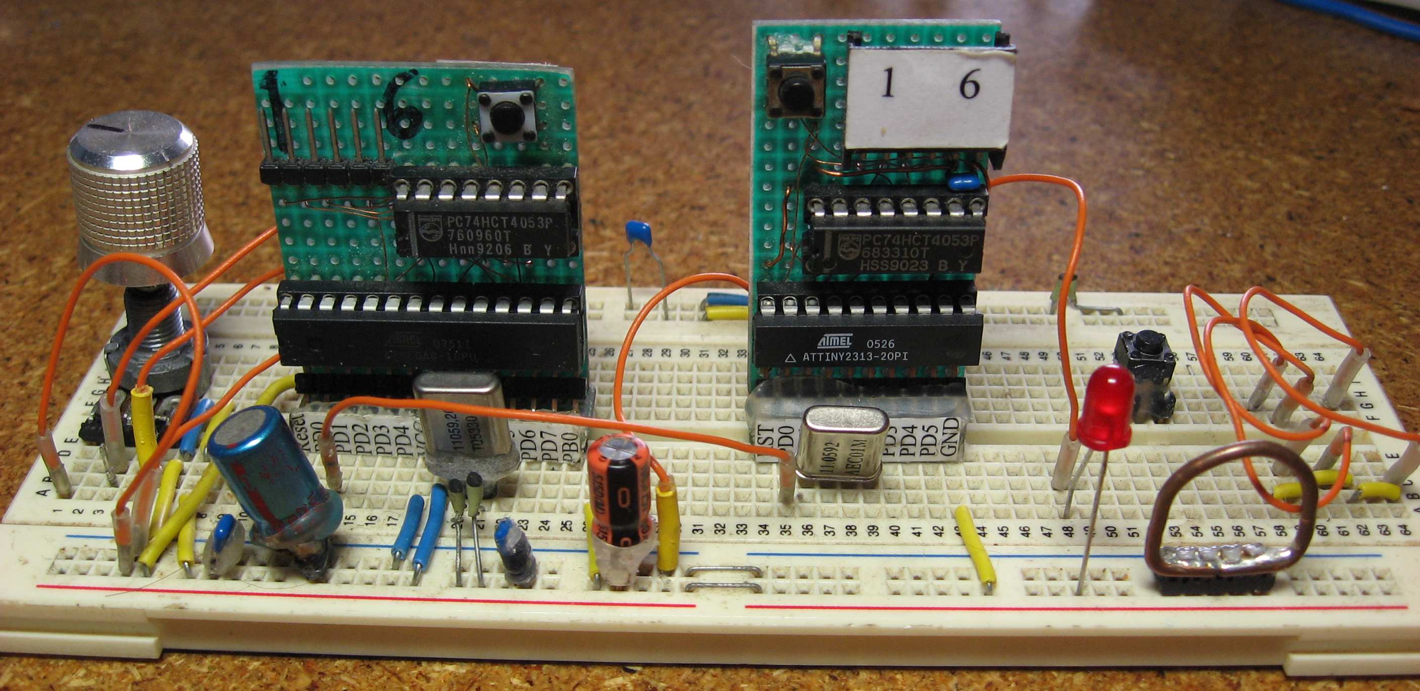
When I’m fiddling about with electronics I want to be comfortable about it. Therefore I built some things to make by breadboarding life a little simpler. One example is the Network Breadboard Interface. Another one is this little project. These little pcb’s can be put directly into a breadboard and they have the same pinout as the AVR it is designed for.
Each of these circuits also has a 74HC4053 and a programming connector on them. The 74HC4053 is from an application note from atmel and it switches the programming pins ( MOSI, MISO, and SCK between the connector on the bottom and the programming connector on the top. The 74HC4053 is switched by the level on the reset pin. I also added a reset button for the microcontroller. I build 3 of these interfaces but the one for the ATMEGA 16 and consorts is not shown on the picture. Also note the small labels for the pin names I glued on to the pcb’s.
The Ground Connection.
On the lower right corner of the picture is a big copper loop. This loop is always connected to the GND of the breadboard and is used to easily connect measurement equipment such as frequency meters, oscilloscopes, and multimeters to the circuit. The ground loop has 2 rows of 5 pins with which it is connected to the breadboard. Only one of those 2 rows are soldered to the loop, the other 5 pins are isolated because they are usually plugged into the 5V rail. If you look carefully you’ll see a similar ground connection on almost every pcb I have made.
The Orange wires
The orange wires on the breadboard are not just ordinary wires. I made a lot of them in different lengths and they have very sturdy gold plated ends on both sides which I scavenged from old headers. They also have some shrink wrap on the ends which I glued in place with hot glue for longevity.
For more detail: Easy Breadboarding using ATMega microcontroller

