Summary of ECE 4760 Final Project Report
This project designs an affordable home security system using an Atmel AVR ATmega1284p microcontroller. It detects intruders by monitoring a continuous infrared beam from a TV remote; if the beam is blocked, a camera captures an image, which is analyzed via edge detection to confirm a human presence. Upon confirmation, the system stores the photo on an SD card and triggers dual piezo buzzers to alert occupants. The design prioritizes simplicity and low cost, utilizing standard peripherals for IR transmission, image capture, storage, processing, and audio alerts.
Parts used in the Home Security System:
- Atmel AVR ATmega1284p microcontroller
- Toshiba CT-90325 TV remote controller
- LTR4206E phototransistor
- LM358 operational amplifier
- C3038 Digital Camera Module (OV6640 sensor)
- Adafruit MicroSD breakout board
- FAT16 formatted MicroSD card
- Pulsing piezo buzzers (high and low frequency)
- STK500 kit
Introduction
Most homes across the world lack a security system of any sort. The goal of our project was to design a simple security system using the Atmel AVR ATmega1284p microcontroller that most people could build without too much hassle for an affordable price. This project uses a few external peripherals to accomplish this goal; many others can be easily incorporated to make the system more useful. In order to make this project more unique compared to other home security systems, we decided to incorporate a camera module for photographic evidence of the perpetrator. We also decided to add in some image processing techniques to try and detect legitimate intruders and ignore false positives.
High-Level Project Description
We have built an infrared (IR) alarm system with the AVR ATmega1284p microcontroller unit. An IR beam is generated by a regular TV remote (for convenience to someone building the project and to avoid having a second breadboard/power supply) that is kept on at all times a door’s distance away from the system board. The system constantly monitors the IR beam, checking if it has been blocked by any object, possibly a human. A detected blockage triggers a camera module to snap a picture and then analyzes whether or not this could an intruder using image processing techniques. Then image is stored on an SD card. A loud buzzer is then triggered for a short period of time to alert people to the intruder. Using any FAT16 formatted MicroSD card inserted in the SD Card module, the owner should be able to transfer the images onto their computer to view them. We went with this idea because we believe that it is a useful and realistic application of the AVR MCU that can be adopted by anyone who is familiar with microcontrollers and doesn’t want to purchase an expensive security system.
Software/Hardware Design
There are five main subtasks to this project: Using infrared light to detect an intruder, taking a picture with the camera module, storing the picture onto an SD card, analyzing the image to detect a valid intruder, and sounding the buzzer. Central to this project is a STK500 kit with an Atmel AVR ATmega1284p that we soldered with parts provided to us by Bruce Land.
IR Detection
Hardware
For IR detection we used a Toshiba CT-90325 TV remote controller as the transmitter of the beam that would be broken. We paired this up with the LTR4206E phototransistor from lab. The remote was kept constantly pressed (this can be simulated in an application environment by taping any remote button tightly pressed) at a door’s distance (around 4 feet) away from the phototransistor. We found that the signal attenuated beyond the phototransistor + comparator circuit’s detection range beyond approximately 5 feet, so a more sensitive phototransistor would need to be used for applications in which a greater distance is required. The remote followed a specific Toshiba Infrared protocol that operates at the 38 kHz frequency band. This involved sending a specific command sequence (at 38 kHz within each pulse) followed by 109 millisecond fixed-width, lower-frequency pulses at (longer) regular intervals to save power. The command sequence lasted for less than a second, but to be safe, we waited for at least 5 seconds before turning on the AVR to ensure a regular pulse stream.
If an object obstructs the path between the remote controller and the phototransistor, the regular pulses will no longer be able to get through to the phototransistor. We detected whether or not a regularly scheduled pulse has been missed as a means of detecting a possible intruder. Although we used a specific remote and IR protocol, any regular, fixed-width pulse stream within the detection constraints posed by the phototransistor should work fine with our system (as will be explained later).
The physical setup of the circuit involved the remote controller on one end and a phototransistor connected to a comparator circuit on the other end. This comparator was hooked up to pin D3 of the microcontroller. This was similar to the circuit we used in Lab 4. The circuit diagram is shown in Figure 2.
We replaced the trimpot in the above diagram to specific resistors so we could have a more predictable threshold to work with, although the trimpot could easily be put back in and adjusted to yield the same threshold. We used an LM358 operational amplifier and a LTR4206E phototransistor. In addition, we decided to add a low pass filter to the phototransistor output to clean up this signal since it was rather noisy. This circuit would trigger every time a pulse occurred. The new circuit diagram is shown in Figure 3.
Software
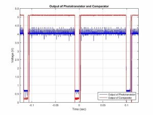
We used the external interrupt 1 (INT1) as the comparator output interrupt which was set to trigger on the falling edge since the phototransistor is active low. The first line of action was to find the period in between regular pulses. After calling the initialize() function that sets up ports and variables required in the code, we call a find_period() function that turns on INT1 and measures the period in between two consecutive pulses in milliseconds. This period is then stored in a global variable for use in other functions and was found to be around 109 milliseconds. Next we created a helper function to count the amount of time in milliseconds between two consecutive falling edges of the interrupt. In our main loop, we kept a timer that would count the number of milliseconds that have gone by. This timer is reset in the interrupt. If the timer exceeds the pulse period (condition relaxed a little for effectiveness), then a pulse was missed and we assumed that the beam was triggered. Since the remote has a “double pulse” as can be seen from Figure 1, we waited past the time of the double pulse (27 msec) before exiting the interrupt. We used the USART to debug this part and also found that milliseconds would be the best choice of measurement. A waveform of the pulses is shown above in Figure 1.
Issues
The main issue we had in IR detection was with the range. The maximum distance between the remote and phototransistor that was acceptable to retain functionality was found to be around 5 feet. Beyond this distance we could still observe pulses being input to the comparator on the oscilloscope, but despite nearly eliminating the hysteresis we could not get the comparator to recognize pulses at these distances. We figured getting a more sensitive phototransistor would help alleviate this issue although since the current maximum range of 5 feet is greater than the average doorway width, we decided that this issue was acceptable given our goal. We also tried shaving off the tip of the transistor to improve direction orientation, but it didn’t make much of a difference. Our comparator circuit had a loose connection somewhere which caused a lot of problems when debugging. However, after replacing an operation amplifier this problem seemed to go away. It is worth mentioning that before using a standard analog phototransistor like the LTR4206E, we tried using a TSOP32138-ND phototransistor specially designed for detecting 38 kHz remote signals. However, its internal circuitry and possible automatic gain control eliminated any regular pulses received while preserving the command sequence (to make it easier for TV receiver circuitry to handle remote signals). It also had lower sensitivity compared to the LTR4206E which was yet another reason to stop using it.
Camera
Hardware/Software
We used a C3038 Digital Camera Module to take an image of the intruder. We researched a lot of different camera modules but most of them required extensive setup to interface and most such components/modules were either not of high enough quality for our purposes or were reported to have many interfacing issues. We finally found the C3038 module (that uses a OV6640 image sensor) and were very satisfied with its easy-to-use I2C interface, flexibility, and documentation. We also found that a previous ECE 4760 group (Ryan Dunn and Dale Taylor, Spring 2009) had used the C3038 camera module with an I2C interface in their 3D Scanner project, so we adapted their code for our project (which also uses Peter Fleury’s TWIMaster for the I2C functionality). The C3038 has a 359×292 pixel array and has amazing flexibility and options for a module of its size and purpose, including variable clock rates, different image formats and resolutions, variable focus and white balance, etc. We used one-line RGB format at a slowed down pixel clock frequency of 69.25 kHz. I2C is a half-duplex communication protocol that while not as fast as SPI (max 400 kbps normal rate), requires less wires and is more than sufficient for many embedded applications and peripherals. The protocol allows for multiple slaves and even masters and although we considered taking advantage of those options, we decided that the complexity and time delay introduced by doing so would not be worth it.
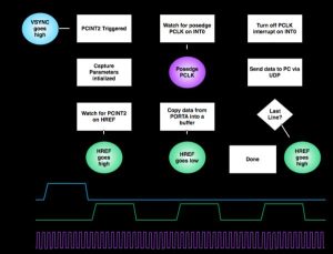
The camera setup can be seen in the circuit schematic in Appendix B. The camera dumps its line buffer into PORTA of the microcontroller. Other important camera ports/pins to the microcontroller include the pixel clock (PCLK) into PIND2, vertical sync (VSYNC) into PINC3, horizontal reference (HREF) into PINC2, I2C clock (SCL) into PORTC0 and I2C data (SDA) into PORTC1. The camera was oriented facing the same direction as the phototransistor to maximize the likelihood of capturing an image of a potential intruder.
Figure 4 illustrates the camera image capture procedure. Given the 8-bit PORTA buffer size, we could send a maximum of one line at a time, but given the fast data rate, it was possible to capture the image and process it in a short amount of time so that the buzzer could be turned on at the presence of an intruder in a timely manner.
Issues
While adapting the code to our project was a little time-consuming, we did not have to go into extensive debugging mode for the camera module or the I2C interface and everything worked fine without too much hassle.
SD Card
Hardware/Software
Instead of soldering wires to an SD card’s pins, we purchased a Adafruit MicroSD card breakout board for convenience. This board performs 5-3.3V level shifting for the MicroSD card voltage requirements, comes with a pin header, and has an onboard LED that blinks when the MicroSD card is read/written that makes it easy to interface with the ATmega1284p. The MicroSD card communicated with the microcontroller via SPI, so the breakout board’s SCLK, MISO, MOSI, and CS signals were connected to microcontroller pins B7, B6, B5, and B4 respectively. We used a 1GB MicroSD card so that we could have a FAT16 file system on it for simplicity’s sake (card sizes over 2GB need FAT32 and will not work with FAT16). We adapted Elm Chan’s popular FATFS code to communicate with the SD Card.
Since the microcontroller only has enough memory to take in one line of an image at a time, we had to save images to the SD card line-by-line. This process begins once the IR circuit is triggered, so an image is saved regardless of whether or not the image processing result says the IR blockage is due to a veritable intruder. Each line is therefore written to the SD Card in the camera PCLK interrupt itself; this does not add too much additional time overhead due to the fast nature of SPI. As for SPI, we set the SPCR of the microcontroller to MCU master and 00 clock polarity/phase (positive polarity and sample on rising clock edge). As per the SD protocol, the clock frequency fed to the SD card is lowered to less than 400 kHz (125 kHz in our case) during initialization but is then increased to 2 MHz (and potentially more) afterwards.
Issues
We had the most issues with getting the SD card to work. The SD card failed to initialize despite apparently correct wiring and code. The configurations were verified (write access, pins, frequency, number of volumes, etc.) and everything seemed fine. The SD protocol was being followed to the letter. We even tried incorporating code found in other projects online which took a lot of time. However, what we realized rather late into debugging was that the microcontroller programmer (ISP) also uses SPI and so the SD card needs to be powered off during this process (whenever the MCU is reset) to avoid corrupting the filesystem. So we tried disconnecting the SD power supply prior to either turning off/reprogramming the AVR and reconnecting it after the AVR was powered up and fully programmed. This ended up working and we were able to save images correctly in Bitmap format. However, we still encountered failures half the time which we have attributed to some hardware issue (and potentially a breakout board failure) that will need further investigation. Our suspicion of a potential breakout board failure was further reinforced when we were unable to program the microcontroller itself when the MicroSD breakout board was connected to the circuit but was not fed a 5V power supply (since both the breakout board and the programmer use SPI).
Image Processing
Software
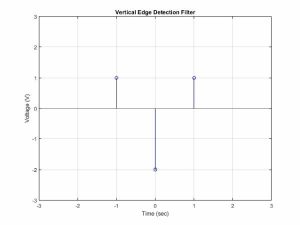
We used image processing techniques on the image to identify whether or not an intruder is a large object (an approximation for a human). To do this, we used an edge detection filter. We passed each line of pixels through a 1-dimensional high-pass filter to strengthen the edges. We then checked to see how many of these pixels were above a certain threshold and added up the number of such pixels across the entire image. If the number of “edge pixels” in the entire image was below a specified threshold, we determine that the alarm was triggered by a large object (probably a human intruder) and proceed to sound the buzzer. We did line-by-line high-pass filtering instead of image-wide high-pass filtering for computational speed and simplicity. Since the camera input can only be read in line-by-line, the entire image would also take much more time (and a majority of the ATmega1284P’s 128K memory) to save and operate on. The discrete-time edge detection filter we used looked like the one provided in Figure 5. Images of the result of this filter are shown in Figure 6.
The high-pass filter computes a difference score that highlights how different a pixel value is compared to its (1D) adjacent pixels. We checked the value of this comparison and if it was lower than a certain threshold (200 worked for us), we then incremented our edge threshold value. We played around with the number of “edge pixels” required to trigger the image until we felt that we got a value that was good enough to differentiate between a plain background and a background with a large human-like figure. A number of “edge pixels” that worked for us was 1250. Since actual human identification is actually very hard, we tried testing in simple environments without that many edges.
To find the threshold for the number of “edge-pixels”, we first found the value of the edges of the background given no interruptions and then added a constant which we tuned to find the difference between a person there and no person. This allowed us to get rid of the background factor and allowed for more complex backgrounds. However, this new method did allow for large ambiguity over whether or not the large object passing through the beam was indeed a human or not, but it would ignore and smaller objects (in any case a large object moving near your door when you’re away is probably something worth looking into).
Issues
One of the main issues with image processing on was the fact that we could not analyze the whole image at once. This severely limited the number of techniques we could try. Most of the good human recognition algorithms are computer vision techniques. Although these techniques could accurately detect people, they were far too complex to be run on a microcontroller not only because additional training images would be needed, but also because the computation time on a microcontroller would be unreasonable. This limited the type of computer vision we could do. Moreover, for ideal edge detection, you would want to detect vertical edges as well as horizontal edges. However, we came up with a high-pass filter for vertical edges only, which seemed to work reasonably well for a simple background and avoided having to save the entire image before processing it. Because this is a rather difficult problem, we allowed for some false positives to come through. Another potential issue is fast-moving intruders; detecting intruders and capturing an image with the camera happen relatively fast, but fast-moving intruders would create image blur that wouldn’t be detected well by the high-pass filter we use. This is a rather tough problem to handle with an 8-bit microcontroller, so we decided to make sure that most “intruders” walked through the beam slowly and could be detected easily for testing purposes.
Hardware
The hardware for this part was relatively simple. We used two pulsing piezo buzzers; one of which produces a high frequency sound and the other a low frequency sound. This combination of buzzers produces unbearable noise that signals urgency (nobody can bear to ignore this noise). The high-frequency buzzer requires 3-8V DC and produces 2.8 kHz sound at 90 dB. The low-frequency buzzer requires 4-8V DC and produces 300-500 Hz sound at 75 dB. We hooked both up to PIND4 and to ground. They were able to generate an alarm sound with just the voltage from the pin.
Software
The software for this part was simple: we turned on port D4 when the conditions for an alarm to be triggered were met, i.e. a triggered image had enough “edge pixels” to warrant containing a human/large object. The alarm was set to ring for 10 seconds and then turn off. The code for this was placed in our main loop after the CV intruder detection code.
Results
IR Beam
The IR beam ultimately worked well. The time in between pulses was short enough that we could catch an object moving through the beam relatively quickly. Given the frequency of the regular pulses, anything that obstructed the beam that wasn’t moving faster than 10 m/s would be caught on camera. Walking speeds and even most olympic track running speed are slower than this so given the enclosure of a non track setting, we are pretty confident that this would be able to detect everyone that walked through the beam would be detected. There were a few times when there were inconsistencies due to some faulty hardware (loose wires, faulty comparator, etc.) but for the most part it worked as planned. The code for this section ran smoothly thanks to the additional factor of error we added on to rectify a potential bad measurement of the pulse period.
Camera
After minor tuning, the Camera as well as the I2C interface worked well. We used the USART to check the pixel values of the camera and confirm that they were reasonable. The camera module could take images, store them temporarily in its onboard memory, and relay them them line-by-line to the microcontroller.The images were of good enough quality for our image processing. Overall, we did not have too many issues with this aspect of the project.
SD Card
After extensive debugging, we got the SD card to save images correctly in Bitmap format, although at times this fails to happen despite disconnecting the power supply to the breakout board before resetting the AVR. We have concluded that this is due to some hardware issue (and potentially a board problem) and will leave the issue for further investigation.
Image Processing
We managed to get fairly accurate image processing with our edge detection filter. It was able to detect whether there was an object up close or no object at all. However, it did not do the best job of distinguishing between a human and a different large object by virtue of the simplicity of our image processing. Small objects posed no problems when passed right through the center of the beam, but as soon as the object became nearly as large as a human false positives were triggered. We did not experiment with relatively small animals like cats and small dogs (rather likely given many people leave pets at home while on vacation), although we expect the system to not generate an alarm in these cases given the camera’s field of view. We decided to focus more on maximizing recall (true positives/(true positives + false negatives)) as opposed to precision (true positives/(true positives + false positives)) since we feel it is more important for every intruder to be detected as opposed to letting intruders get away for less false alarms being called. We also realized that computer vision in general is a very difficult problem for even full computers and given the limitations of the microcontroller, we did the best we could. Overall, we were pleased to find that relatively simple high-pass filtering worked well for person detection.
Buzzers
The buzzers were loud enough to alarm of and scare away intruders. It even startled others working in the lab or other in the area in which we happened to be working on the project. Of course, one issue the buzzers raise is that they informs the intruder of the presence of a simple security system they can dismantle (or steal for their own purposes). This issue hopefully pales in comparison to the frequency the home is broken into and to the effectiveness in raising alarm to neighbors/passerby/police who may proceed to nab the intruder.
Safety
There were a few times in this lab where safety had to be enforced. Initially we were planning to use a powerful IR led lamp as the infrared beam that could actually cause damage to the eyes. This lamp was originally intended for the purpose of night vision. However, we realized that this lamp could actually cause eye damage if looked at directly and so decided that it would not be the best idea to use this lamp for the project. Besides this, we also made sure not to have any loose wires coming out of our project. Overall, our project was relatively safe.
Usage of Product
Overall, the device is fairly easy to use. After setting up a constantly pressed remote and turning the microcontroller (with a power supply) on, the system requires no further user interaction. It will perform the tasks it needs to without any more user input (besides the intruder breaking the beam). As mentioned before, we tested the system by holding down a remote key to generate a constant IR pulse stream but in actual practice, we would probably tape a remote button down to achieve the same. This ease of use was purposefully intended since security systems should ideally not require much intervention from their users and should quietly run in the background. It is important to note that the system requires a 5V power supply which means that either the house mains must be turned on or the user may have to seek some alternative power source that works with the STK500 power port. This may be an issue for those who want to turn off mains power before going on vacation but not so much so for those who want to use this system every night as a regular security system.
Conclusions and Further Ideas
Using simple household items, a few cheap components from lab, and a few relatively cheap external peripherals, we were able to make a competent security system that can detect intruders pretty accurately. The main difficulty of this project came from detecting the pulse stream accurately as well as from adding and interfacing peripherals onto the microcontroller. Integrating code (in the case of the camera) proved to be tricky at times due to either insufficient documentation or due to specificities of the project it was adapted from.
Some ideas we have for improvement mainly involve additional peripherals we could add on to the project. For instance, sending a message to the owner via Bluetooth (or even better, through cellular). We initially thought of trying out Bluetooth communication and set up a Bluetooth module, but since both the camera and the Bluetooth module would then be utilizing the same I2C interface, we decided against the complexity of having multiple I2C slaves especially since the Bluetooth module didn’t really provide that much additional functionality given the buzzers. Other ideas were not implemented due to lack of resources (given the project budget) or time. Another thing we would have liked to improve on is the range of the IR beam detection. Although our range is fine, we realize that it could be a lot longer if we used another circuit from across the room. This would however have required either another power supply and breadboard (which could have put us over our budget) or . Another thing we could’ve tried is trying to send an image or message to a cell phone once the alarm has been set. We initially planned for a message to be sent via bluetooth, but once we learned of its limited range, we realized it would not be practical in use and it would just be better to use buzzers instead since repeated noise could scare off an intruder. If possible, we would like to try a longer range of transmission to alarm when you are away from the house.
Societal Impact
The alarm system we have designed will allow homes to be much more safer when people are out of the house or asleep. This device would also take a picture of intruders which would allow house robberies and other crimes inside the house to be documented with photo evidence. This would make it easier to identify suspects of these crimes and allow more people to be caught for their crimes. Even if they are wearing a ski mask and other identity-concealing clothing, a picture of these articles of clothing may help for detecting criminals. The alarm with the system can give people a secure feeling when sleeping. Besides legal reasons, this will also give people a more comforting feeling about home security and allows them to sleep in peace.
Regulatory Standards Used
SPI protocol, the I2C protocol, Toshiba CT-90325 IR Protocol, FAT16, and SD Standard.
Intellectual Property
The idea for this project is attributed entirely to Professor Bruce Land, teaching ECE 4760. However, the design and implementation of this project is our work. We used FatFS code that is distributed under the GNU General Public License to communicate with the SD card and and we take no credit for these parts. There are probably no patent or publishing opportunities for this project. This is a useful project that can be built and adapted by anyone who wants to design a simple security system behind a particular door of a building.
Ethical Considerations
Security systems are pretty much everywhere in our world so it is hard to take credit for this concept. However, our implementation is different in that we use a camera and perform image processing on the taken image. More importantly, we present . When doing this project, we decided to do it our own way, and made no reference to any projects online in which they also designed a security system.
Datasheets and Standards
1. Atmel AVR ATmega1284P: http://www.atmel.com/images/doc8059.pdf
2. C3038 Camera Module: http://www.electronics123.net/amazon/datasheet/c3038.pdf
3. FatFS: http://elm-chan.org/fsw/ff/00index_e.html
4. Secure Digital Association SD: https://www.sdcard.org/downloads/pls/simplified_specs/archive/partE1_200.pdf
5. LTR4206E: http://optoelectronics.liteon.com/upload/download/DS-50-92-0073/S_110_R4206E.pdf
6. Adafruit MicroSD Breakout Board: https://www.adafruit.com/products/254
7. SPI: http://www.ee.nmt.edu/~teare/ee308l/datasheets/S12SPIV3.pdf
8. I2C Source: http://homepage.hispeed.ch/peterfleury/avr-software.html
Acknowledgements
We would like to thank Bruce Land and all the ECE 4760 Fall 2014 TAs Alexander Jaus, Syed Tahmid Mahbub, and Eileen Liu for their invaluable support and great company throughout the course of this project. We would also like to thank Ryan Dunn and Dale Taylor for camera code from their Spring 2009 ECE 4760 3D Scanner Project.
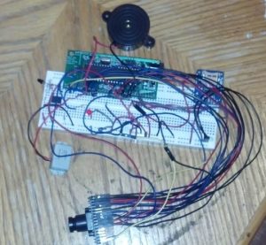
Appendix A: Photos
Source: ECE 4760 Final Project Report
- How does the system detect an intruder?
The system uses a TV remote to generate a constant infrared beam; if an object blocks this beam, the microcontroller detects the missing pulse and triggers the alarm sequence. - Can the system distinguish between a human and other objects?
The system uses a 1D high-pass filter to count edge pixels; if the count exceeds a specific threshold, it assumes a large object like a human is present. - What type of memory card is required for storing images?
A FAT16 formatted MicroSD card is required because cards larger than 2GB need FAT32, which is not compatible with the adapted code. - Why was the TSOP32138 phototransistor not used?
The TSOP32138 was discarded because its internal automatic gain control eliminated regular pulses and it had lower sensitivity compared to the LTR4206E. - How long does the alarm sound when triggered?
The alarm is set to ring for 10 seconds before turning off automatically. - What caused issues with the SD card initialization?
The microcontroller programmer also uses SPI, so the SD card needed to be powered off during the reset or programming process to avoid corrupting the filesystem. - Is the IR beam range sufficient for a doorway?
Yes, the effective range is approximately 5 feet, which is greater than the average doorway width. - What communication protocol does the camera use?
The C3038 camera module uses the I2C protocol for communication with the microcontroller.