Summary of EYEMouse ELECTRO-OCULAR CURSOR CONTROL
The article details the "eyeMouse," a proof-of-concept device using Electrooculography (EOG) to control a cursor via eye movements. It overcomes infrared safety concerns by measuring corneoretinal potential differences with dry electrodes. The system amplifies microvolt signals, filters noise using low-pass and high-pass filters, isolates the user from mains power via an optoisolator, and processes data on an ATmega1284p microcontroller to drive a TV display. While vertical control was limited, horizontal tracking demonstrated hands-free cursor movement comparable to a mouse.
Parts used in the eyeMouse:
- Dry contact electrodes
- Electrode cream
- Sticky pads for electrode placement
- 9V battery
- Texas Instruments INA121 instrumentation amplifier
- LM358 operational amplifier
- IL300 linear optocoupler
- 2nd order low pass filter components
- 4th order low pass filter components
- High pass filter components (RC circuit)
- ATmega1284p microcontroller
- Analog-to-digital converter (ADC)
- Small TV screen
- Zener diodes (for USB voltage regulation)
Introduction
Several different approaches have been explored in developing a system to track eye movements. These approaches span from measuring reflections of infrared light to using advanced imaging techniques to monitor specific features within the eye. While a variety of reports exist on measuring infrared reflections off of the eye, the long term effects of illuminating the eye with infrared LED still remains questionable. Eye tracking has been successfully implemented using video and imaging techniques; however, the implementation of such a system is quite complex and requires advanced knowledge of such types of signal processing.
Recently, electrooculography (EOG) has gained more attention as a suitable method for successfully tracking eye movements. The lens of an eye at the cornea focus light at the retina, which houses seven layers of alternating cells used to convert the incoming light into a neural signal that generate receptor potentials. The retina essentially acts as a bioelectric generator, creating an electric field in its surrounding volume which serves as a conductor. Because of the higher metabolic rate at the retina than the cornea, the cornea and retina together acts as a dipole with the cornea being electrically positive with respect to the retina. The resting potential between the cornea and retina has been measured to range from 0.4 mV to 1 mV, aligned along the optic axis. Consequently, this dipole potential rotates along with the gaze of the eye. Electrooculography uses electrodes placed close to the eyes to take advantage of this corneoretinal potential. By placing two electrodes on opposing sides of the eyes, the difference in potential measured by these electrodes changes as the eye moves. As the angle of rotation of the eye increases, aligning the optic axis with the electrodes, the signal amplitude coupled onto the electrodes also increases. Typical voltage magnitudes range from 5-20 uV/ ͦ of rotation of the eye. With proper calibration and electrode placement, the position of the eye can be determined with an accuracy of +/- 2 ͦ vertically and +/- 1.5 ͦ horizontally. As the eye sweeps angles greater than 30 ͦ, however, the linearity of the voltage magnitude worsens. In industry, EOGs are used for ophthalmic diagnosis and enhancing the eye movements of digitally created characters in film
The eyeMouse is a proof of concept device using the principles behind EOG to control a cursor on a monitor strictly with the user’s eyes. Using five electrodes placed on the head, the user can control the on-screen cursor simply by looking at the exact position they want the cursor to move. The goal of the project was provide cursor control comparable to a traditional USB mouse providing the user with a hands free method of interacting with their monitor. The hope was to successfully implement smooth and continuous control of a cursor to prove that such a device could be extended to be used to replace a mouse for a computer screen.
High Level Design
Motivation
In choosing our project, we hoped to develop a product that would have practical application and could be used to actually help people. We decided a project that would be interesting and instructive would involve motion tracking. After pitching several ideas based off of motion tracking to Bruce Land, he told us of a measurement technique called electrooculography and mentioned he had the dry electrodes needed to perform the associated measurements.
We soon decided that a particularly intriguing project would be to see if we could control the cursor on a computer screen with someone’s eyes using the signals obtained from the electrooculography measurement method. The motivation behind this project was rooted in both our interest to develop a wearable device like Google Glass and in our desire to develop a product that would actually have practical application to help people.
Many paraplegics and amputees are constrained in their day to day activities because of paralysis or absence of their limbs. We wanted to develop a way where they could instead use their eyes to realize the same functional tasks they were originally hindered from. The eyeMouse was chosen because it would create a human to computer interface where such subjects could still be able to use and control a computer without the need for any hands. Unfortunately, because we were unable to get the communication between our microcontroller and computer working within the time constraints of this project, we re-tailored our project to control a cursor on a small TV screen directly connected to the microcontroller. This was to serve as more of a proof of concept that smooth cursor control could be obtainable purely through eye movements. With such an interface successfully implemented, the same functionality could easily be extended to a computer mouse if the USB communication with the computer could be achieved. Furthermore, this idea could be extended even further to provide motion control with the user’s eyes to more physical objects. Several reports have been published about attempts to use EOG’s to control wheelchairs—something with a clear and very practical purpose.
Overview
The final implementation of our project allowed ocular control of a cursor on a small TV using NTCS standards. A very basic, high level diagram of our entire system is mapped in Figure 1 to help visualize our proposed idea.
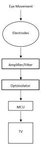
As seen by the outline in Figure 1, the whole system worked as follows: The input into the system was eye movement from the user. These movements, or changes in potential, were picked up as electrical signals by the electrodes. In order to properly process and extract useful information from these signals, they were then sent to some sort of amplifying and filtering circuit to boost the voltage levels and attenuate noise in the measurements. This was necessary to improve the signal to noise ratio. Once a clean signal was obtained, the signal needed to be isolated from the rest of the system so that it could be sent to the MCU to be processed without presenting any safety hazards. The MCU, coded with some internal logic, would perform a variety of calculations based on the signal input received from the filter and output commands to the TV to control a cursor on the screen. This whole process was continuously running so that the cursor position would be updated in real time as the user moved his or her eyes across the screen.
Background Math
The voltage magnitude read by the electrodes were proportional to the angle the eyes of the user moved. The potential change seen near the eyes is about 5-20 µV/ ͦ depending on the user and environmental conditions. If the exact value of the potential change per degree of rotation could be found through calibration, the voltage readings could easily be mapped to correspond directly to a cursor position on the TV screen. The vector math required is rather simple and illustrated in Figure 2.
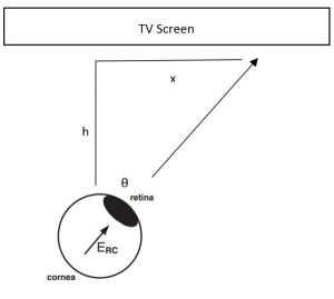
With the angle θ known, mapping the cursor onto the TV screen merely requires a simple trigonometric calculation. The value x on the TV screen the eye is looking at can be found by using the equation:
This idea can be extended to two dimension by using this equation for two different angle measurements. If two readings were taken, one measuring the horizontal angular position of the eye and the other a vertical position, a (x, y) coordinate on the TV screen can be found—exactly where the cursor must move to.
In order to find the angle swept by the eye from a voltage reading by the circuitry, a Riemann sum was utilized. The signal read by the MCU corresponds to the AC component of the electrode signal. This signal measured the rate of change of the eye’s potential, but not the change in potential itself. The change in potential corresponded to the area under the peaks observed in the AC signal, or the integral of the signal. In order to find this, a Riemann sum was executed.
A Riemann sum is basically a numerical approximation of an integral that finds the area under a curve by breaking it up into small rectangles and adding up all the individual areas. Figure 3 is an illustration to help visualize how the Riemann sum works.
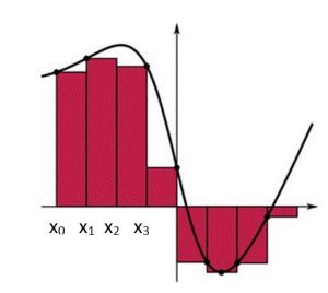
If the curve under examination is partitioned into intervals of {[x0, x1], [x1, x2], [x2, x3], …} then the area of each rectangle can be found by using the equation:
The area under the curve can then be found by summing all the individual rectangle areas. In other words:
If the signal from the electrodes was read by the MCU through its ADC, then it would receive many samples of the curve, each corresponding to a (xi, f(xi)) value. By taking a Riemann sum of these sample points, the area under the AC signal would be obtained and the change in potential could be found.
Hardware
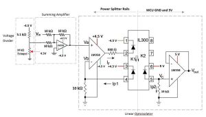
Figure 4 shows a high level schematic of a single channel of the hardware involved in measuring the signal output of the electrodes. One channel was used to read horizontal eye movements, and the other to read vertical movements. The basis for the design was inspired by the Spring 2015 EyeSnake video game. While the design of the EyeSnake game was first replicated to help build an understanding for the circuitry involved to read measurements from the electrodes, several modifications were made and a few stages were added. The final design decisions are justified and problems encountered described
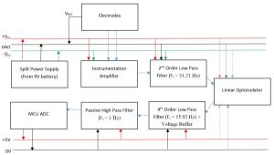
The voltage signals from the eye detected by the electrodes lie within the microvolt range and so were heavily influenced by noise. Each channel consisted of two electrodes, one which would be exposed to the positive side of one eye’s cornea and a second which would face the negative side of other eye’s cornea. Thus, it was desirable to amplify the potential difference between the two electrodes as a means of determining eye position. An instrumentation amplifier was used in order to reject noise common to all the electrodes while boosting the differential input. For safety, it was necessary that any circuitry hooked up to a user’s head had absolutely no path to a power outlet in order to eliminate even a small possibility of an electrical surge to the head. Consequently, a new ground needed to be created. A split power supply topology was used to split the potential of a 9V battery around a reference voltage (the new ground) into two rails 4.5V above and below the reference. This allowed both positive and negative output values to be realized by the circuitry. The single ended output of the instrumentation amplifier was then fed to a 2nd order low pass filter with a 32.21 Hz cutoff frequency in order to filter out noise, especially the 60 Hz noise coupled from other electrical equipment nearby. A linear optoisolator was then designed so that the preceding stages which shared paths connected to the user’s head were completely isolated from the MCU which ran off a DC power supply from an outlet. This also allowed an oscilloscope to be used on the MCU side of the hardware for testing purposes. On the other side of the optoisolator, the signal was passed through a 4th order low pass filter with a cutoff frequency of 15.92 Hz followed by a voltage buffer to help strengthen the signal. Finally, a simple high pass filter with a time constant of 1 second was used to remove any DC offset from the output signal before being fed into the MCU ADC ports used to interpret and utilize the signal extracted from the electrodes.
It should be noted that throughout the design and implementation process, the circuitry was retested incrementally with the addition of each stage by using an ideal signal. A sine wave generator was used to produce a sinusoid that was fed to a voltage divider of two 100 kΩ resistors connected in series by a 75 Ω resistor. The voltage across the 75 Ω resistor was taken as the differential input into the system with the ground of the sine wave generator as the VREF. By using the voltage divider described, the sinusoid input amplitude was reduced by a factor of about 2667, allowing voltage signals on the same order of magnitude as those measured from the electrodes to be simulated.
Electrodes
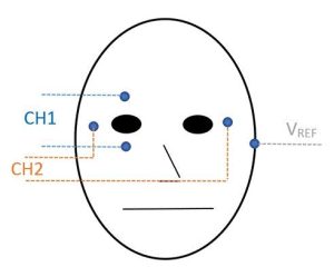
Dry contact electrodes were used in conjunction with electrode cream to improve conductivity. Each electrode was attached to a small sticky pad that was used to keep the electrodes in place and tight on the user’s face. Five electrodes were used and placed on the user’s face as depicted in Figure 5. Two channels of signal information were taken using the five electrodes. Channel 1 took the differential input from electrodes on each side of the user’s head in line with his or her eyes in order to measure changes in the horizontal position of the user’s eyes. Similarly, channel 2 measured vertical movements of the eyes using two electrodes above and below the center of one of the user’s eyes. Finally, a reference voltage was taken from an electrode placed behind the user’s ear to provide the isolated side of the circuitry with a ground around which the voltage from the battery was split. The optimal placement of the reference electrode varies across literature, so the position used with this device was determined through experimentation. While it originally seemed that the best location was on the user’s forehead, it was decided that this was too close to the other electrodes and may pick up differential signals we wanted to amplify.
Split Power Supply
In order to split the voltage of a 9V battery around a reference voltage, the circuit in Figure 6 was implemented. This topology was taken from the EyeSnake video game except with 1 µF capacitors used between the output and rails instead of 0.1 µF capacitors. Two 1 MΩ resistors were used in series as a voltage divider to provide a midpoint between the voltage delivered by the battery. This midpoint was to serve as the ground for the isolated side of the circuitry connected to the user’s head. High resistance values were chosen so they would not draw too much current. A 1 nF capacitor was placed in parallel with these resistors to filter out high frequency noise of the battery. Because the output resistance of the voltage divider connected to the battery was large, an LM358 operational amplifier was used with a negative feedback loop to act as a voltage buffer. This way the output impedance of the split power supply as seen by later stages would be lower.
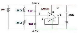
Although the schematic this design was based off of called for 0.1 µF capacitors to be placed between the voltage rails and the output of the buffer, it was determined that larger values were needed. After the addition of a couple more stages, non-ideal effects of noise were seen at the outputs of the operational amplifiers in the form of inconsistent readings often met with voltage clipping. It was determined that the problem was due to variations in the voltage provided by the battery. The voltage rails extending from the battery decreased over time and were susceptible to noise. Because the ±4.5V rails from the battery were used for the amplifiers in the first few stages, power supply noise resulted in unwanted variations in the outputs of the amplifiers. By increasing the capacitor values from 0.1 µF to 1 µF, more high frequency noise in the voltage rails was forced to ground, thereby maintaining a more stable power supply. After switching these capacitors, a much more stable output from the amplifiers were observed.
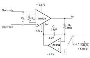
Instrumentation Amplifier
Texas Instrument’s INA121 was chosen to be used as the instrumentation amplifier due to its high common mode rejection. A resistance value of 330 Ω was chosen as the RG between the 1st and 8th pin of the INA121 instrumentation amplifier giving a gain of about 152.5. Originally, the reference voltage at pin 5 was designed to be controlled by a potentiometer between its ±4.5V rails. This would add an opposing DC value to the input signal’s offset in order to ensure that the instrumentation amplifier was always operating in its saturation region. Because the pre-existing DC offset of the input signals to the INA121 from the electrodes would vary based on the user, environmental conditions, temperature and other factors, the potentiometer had to be adjusted frequently to maintain proper biasing on the INA121. This turned out to be quite a nuisance and decreased the usability of the device; a more automated way to achieve the proper voltage reference was desired. The potentiometer was replaced with the AC-coupled instrumentation amplifier topology provided by the INA121 datasheet. Figure 7 illustrates the final schematic used for this module. By AC coupling the instrumentation amplifier and removing whatever DC offset was present in the electrode signals, it could be ensured that the amplifier always remained in saturation. This was achieved by essentially making a high pass filter with a very large time constant. A resistor and capacitor with the values shown in Figure A-3 were connected in series between the output of the INA121 and its reference. The node shared by the resistor and capacitor served as a low pass filter with a cutoff frequency of 1.59 Hz. By comparing this voltage to the ground on the isolated side using an LM358 amplifier, the amount of DC offset of the Vo signal relative to the VREF electrode was output the LM358. By feeding this into the reference of the INA121, the unwanted DC offsets in the measured electrode signals were essentially zeroed out—AC coupling the system.
2nd Order Low Pass
Now that the differential input of the electrodes had been amplified, two things were still needed. More gain was preferable to help boost the signal from the electrodes and a filter was needed to get rid of extraneous noise, especially the 60 Hz noise from surrounding electrical equipment. After some research, it was found that the frequency of EOG signals from the eye typically fall in the range of 0-30 Hz. While the first implementation based of the EyeSnake video game had two separate stages to boost gain and reject noise using an inverting amplifier and first order low pass filter respectively, a 2nd order low pass filter was used in the final design. The resistance and capacitance values were chosen to give a cutoff frequency of 31.21 Hz and a gain of 2. A schematic of the filter used can be found in Figure 8.
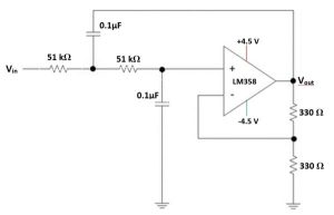
Because the gain of two amplifiers in series multiply, the combined gain of the instrumentation amplifier followed by the low pass filter was 305.This stage was originally designed to provide even more gain to further boost the input signal of the electrodes; however, when the whole completed circuit was tested with the electrodes, clipping was observed on the output signal. Instead, a little more gain was added at the final stage to give a larger signal magnitude input into the ADC of the microcontroller while avoiding clipping in the preliminary stages. Because we were unsure of the exact amplitude levels the electrodes output, we wanted to build the circuit to be compatible with a decent range of input magnitudes.
Linear Optoisolator
As mentioned earlier, it was imperative that the circuitry connected to the electrodes on the user’s head had no physical connection to a power outlet. Such a situation would be hazardous to the user’s health if the circuitry experienced voltage or current spikes from the outlet. The next stage built was an optoisolator. By taking the electrode signal and mapping it onto the other side of the optoisolator, an oscilloscope could be used to look at the actual signals obtained and amplified from the electrodes. These signals would also be able to be used with an MCU using a DC power adapter from a wall outlet.
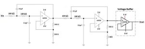
At first, the 4N35 optoisolator was used to optoisolate the electrode side of the circuitry based off the design in the EyeSnake video game. While an output was obtained, it was soon determined that the output voltage was not a linear function of the input current through the photodiode. If a smooth and continuous mapping from the user’s eye position to a mouse was to be achieved, a more linear optoisolator configuration was needed. The 4N35 optoisolator was switched out with the IL300 linear optocoupler which used an additional feedback photodiode to help linearize the output. The corresponding application circuit from the IL300’s datasheet was built. Much time was spent tuning the component values of this subsystem in order to successfully achieve an acceptable output. It was determined that if the input voltage at node Va did not have sufficient DC bias, not enough current would pass through the photodiode to induce a current on the feedback and output photodiodes. Because an AC coupled instrumentation amplifier was designed at the first stage, the input signal into the opto-isolator circuit had little to no DC offset. In order to remedy this, a voltage divider was used in conjunction with a summing amplifier in order to add a DC value to the input signal being received. A schematic of this entire system is shown in Figure 9.
It should be noted that the 10 kΩ potentiometer could be used as a voltage divider itself without the additional 5.1 kΩ. Such a design may prove more robust as the current voltage divider introduced an unnecessary path from the batteries upper rail to the reference ground through one of the 5 kΩ resistors of the potentiometer; this was unintentional and not realized during the implementation of this circuitry. It should be noted that when changing the value of the potentiometer in the second channel, the signal in the first channel was sometimes affected. While this could be the result of a short somewhere in the breadboard, the reason for this may be better explained by the current sunk in the path from the 4.5 V rail to ground. As the resistance of the potentiometer was changed, the amount of current drawn from the battery also changed. This would cause variations across the battery’s voltage. Any circuit devices used without a good power supply rejection would be particularly susceptible from such an occurrence. Also, when turned to one of its extreme values, the potentiometer would kill the signal in the adjacent channel. This most likely corresponds to when the potentiometer is set to its lowest resistance, effectively shorting the upper rail and ground together. The LM358 employed three 10 kΩ resistors in order to build a summing amplifier that added equal portions of the input signal and offset without any gain.
The resistors at pin 4 and pin 5 were chosen to be 10 kΩ. These resistance were held to the same value so that the output of the IL300 optocoupler would be the same as the input without any additional gain or attenuation. Although, the IL300 datasheet recommended that the 10 kΩ resistor on the LM358’s inverting input should be connected to the same ground as the amplifier’s, the best output signal was obtained found by giving the LM358 the -4.5 V rail as a ground, and connecting the resistor to the reference voltage from the user’s electrode. The LM358 on the output side was used as a voltage buffer per the schematic on the datasheet. It was important that the output side of the IL300 and rest of the proceeding circuitry only used the MCU ground and voltage rail so as to avoid any direct connections to the user’s head.
4th Order Low Pass Filter
After the signal had passed through the optoisolator, it was observed to be fairly noisy. Another low pass filter would be needed in order to filter out additional noise picked up in the earlier stages. At this point in the testing process, it had been noticed that when a user was to move his eyes in a certain direction a peak would sometimes be followed by several more peaks that were both faster and larger in amplitude than the typical values observed. This most likely occurred because the user could not realistically keep his eyes perfectly moving in a single direction. After moving one’s eyes to a fixed location, they tend to oscillate a little around that point adding unwanted signal information to the output. To account for this, the frequency of the actual slower eye movement across a computer was measured with an oscilloscope and found to be somewhere between 3-8 Hz. Although much literature had stated that eye movements can range up to 30 Hz, it was determined that for the purposes of moving a cursor, a lower cutoff frequency could be used. Thus, the 4th order low pass filter of Figure 10 was built with a cutoff frequency of 15.92 Hz. This lower cutoff was used to not only filter out additional noise, but also unwanted eye oscillations that impede a smooth transition from looking at one location to the next. A little gain was also added to this filter to give a larger range of values to be read by the ADC of the MCU in the final stage of the circuitry This filter had a cutoff of 15.92 Hz and a gain of 2.
The use of a 1 MΩ resistor on the output of the 4th order filter gave it a high output impedance. In order to prevent loading issues, a voltage buffer was added at the end which seemed to help draw a stronger signal. While the cutoff frequency of the first low pass filter before the optoisolator could have also been lowered to 15.92 Hz, after adding this stage, the output signal being read into the MCU was fairly strong and clean, and so it was left as is. Changing the cutoff could have possibly helped filter out a little more noise, but it was decided that this probably would make too much of a noticeable difference.
High Pass Filter
The output of the 4th order low pass filter produced an acceptable waveform to be read by the MCU in terms of amplitude and noise content. All that was remaining was to take off the DC offset of the waveform. This was so movement in one direction would correspond to a positive voltage and movement in the opposing direction would output a negative voltage. In order to achieve this, a simple RC high pass filter with a very high time constant was used. With a 1 µF capacitor and a 1 MΩ resistor, the high pass filter used had a cutoff frequency of 1 Hz, therefore rejecting any DC values in the signal but maintaining the desired content from the eyes.
Software
Initial Procedures
We approached the software component of our project with an incremental design and test procedure. The software component of this project, specifically eye tracking, begins with amplified electrical signals as inputs to the atmega1284p. In a previous assignment during the semester, we obtained experience with the onboard analog-to-digital converter as a method of receiving user inputs while implementing a video game. To analyze and quantize the two differential inputs of left/right and up/down eye movement, we determined at least two ADC conversions would be necessary as well as optimizing code execution time to compensate for relatively long latencies during conversions.
We began our program design with ADC conversions on two separate input port pins, each receiving input voltages, ranging 0V – 5V, controlled by 10kOhm trimpots. To perform conversions on different inputs in succession, the MCU’s four LSBs of ADMUX, analog to digital multiplexer selection register, were set to select channel 0 corresponding to port A.0 and the MSB set for a reference voltage of 5V. Conversions were started by raising the ADSC bit of ADCSRA, ADC status register A, and after completion of the first conversion, the four MSB’s of ADMUX were manipulated to represent seven in binary, changing the input to channel 7, port pin A.7. The program alternated ADC inputs within an infinite while loop, printing conversion values from ADCH, ADC data register high, to an LCD. Values ranged from 0 – 255 because ADLAR, left adjustment bit, was set to one in ADMUX to limit the precision to 8-bits and decrease conversion time. Having two constantly running ADC conversions and their outputs displayed, we decided the next step in our software component was to establish serial communication between the eye tracking and HID MCUs.
Serial Communication
Our original goal was to configure a MCU so it could be recognized, without additional driver software, as a USB HID mouse by PCs running Windows/Mac/Linux operating systems. V-USB is an open source development website with HID project examples and source code allowing most Atmel MCUs to be recognized as a USB mouse, transmitting cursor coordinates, click types, and scroll wheel parameters. The V-USB source code, when configured for the specific MCU, emulates a logitech mouse and performs all the necessary USB protocols to transmit mouse parameters. The source code was lengthy because USB protocol is complex and the host operating system must continuously recognize the Atmel chip as an HID. This requires a heavy load on the MCU’s processor and therefore a second atmega1284p would be necessary. Before configuring the second MCU as an HID, we needed efficient and fast communication between the eye tracking and HID MCUs.
Utilizing UART code provided to us by Bruce Land in previous assignments in the course, and tiny real-time kernels (TrT) written by Dan Henriksson and Anton Cervin, serial communication was established between the two MCUs transmitting message packets formatted as “%Xval %Yval %Click?”. An filestream was configured as the stdout/stdin I/O buffers of the MCU. Packets containing formatted messages were transmitted by printing to the output stream buffer using fprintf. On the receiving end, the HID MCU used fscanf to read and unpack formatted messages on the stdin input buffer. Incremental testing verified the functionality of each MCU before connecting their receive/transmit buffers (RX/TX).
The serial communication application puTTy was a useful tool to send messages to the receiver MCU and display transmitted packets from the other MCU. The issues encountered while establishing serial communication mostly involved improper time constraints. While transmitting packets was simple to implement, the receiver often displayed incomplete messages or erroneous characters. The solution was involved changing the placement of semaphores that improperly protected shared data, allowing the kernel to schedule tasks that would interrupt the serial communication being done within another task and manipulate the mouse parameters. Upon verification, the serial communication transmitted two ADC conversion values from trimpots as xval/yval, and a hardcoded value for click as a placeholder. With LCDs as a debugging tools, we could see ADC conversions displayed on eye tracking MCU also visible on the HID MCU’s LCD, confirming that serial communication was established. The eventual goal was to unpackage these messages and use these parameters as inputs to V-USB mouse functions.
USB HID Mouse
After establishing serial communication, focus shifted to implementing the V-USB HID mouse example code. To connect the HID MCU to a PC, we connected ports D.2/D.4 on the atmega1284p to the D+/D- wires of a USB serial cable. It is USB protocol that D+/D- signals are +/- 3.3V, but the MCU can only output at discrete logic levels of 0V and 5V. To reduce the potential of signals from the port pins, two 3v6 Zener Diodes were used and the D+/D- wires received the desired +/- 3.3V.
Understanding the different source, header, and make files included in the downloadable V-USB folder was a difficult task and proved to be overwhelming. Intense research and following past ECE 4760 projects, including the Wireless Tilt Mouse by Jack Ellsworth and Skyler Schneider, gave us some insight on how to decipher the readME files included in the V-USB folder. The USB configuration header file contained many configuration options for the device, specifying I/O ports used for the USB interface and the presence of pull-up resistors are just to name a few. The real difficulty came involved understanding the use of make files and properly programming the MCU for HID operation. With the deadline approaching and the eye tracking portion of our project requiring much work, we abandoned the HID element and decided to control a cursor on a small TV screen, a device we had experience with already. Our progress implementing HID ended with the PC able to recognize the presence of an unknown USB HID device, likely a result driver issues preventing transmission from HID device to the PC. With more time, we believe implementing the HID device could be accomplished. Downscaling the project to controlling a cursor on a small TV preserved the main goal of the final project, exploiting electrooculography to achieve smooth cursor movements with only our eyes.
Pulse Sampling and Integration
The lessons learned in the earlier days of the project proved very helpful in software development for the eyeMouse. Difficulties before achieving consistent and accurate serial communication of ADC conversions forced us to do our reading, leading to many hours rereading portions the atmega1284p datasheet. The most notable of sections we reread was the ADC operation. An assignment earlier in the course required us to implement ADC conversions under tight time constraints to remain in sync with the TV’s refresh rate of 60 Hz. We used our assignment’s source code, derived from example code by Bruce Land, as a base for our project because synchronization tools were already in place. The constraint on time tightened even more when we later implemented differential ADC conversions, several clock cycles slower than single input conversions, within the same refresh rate. The next step was programming the MCU to sample incoming pulses with the ADC, process their magnitudes, and perform Riemann sums over the signals.
As mention before, the area under/above each signal produced from the eyes’ differential potential relates to absolute position on a screen. In our program, the left/right and up/down differential potentials, were sampled, integrated, and analyzed before printing the cursor’s position on the TV. To integrate over AC signals, the voltage was sampled on each refresh of the TV. A pulse 250 ms in length could be sampled at 30-45 points before dropping below the threshold. The refresh rate of 60 Hz spaced samples by 16.667 ms, the time requirement for ADC conversions on both input signals. Originally we decided to use two single ended input channels on ADC and a reference voltage of 1.1V because we believed the 200mV-400mV amplified eye signal was large enough to generate a respectable range of conversion values peaking at 115, almost half the max value of 255. After some time, we realized the limitations on cursor precision that would entail and due to complexity in our amplification/filtering system, introducing more gain into our circuit would lose the desired shape of the pulses.
To overcome this, we decided to use the differential gain function of the ADC. Differential gain conversions are slightly slower than single inputs because some hardware overhead from gain stabilization latency and parallelism of conversions on two inputs. We did not need to compare the differential signal from the eyes to another signal but were insistent on using the 10x amplification of the ADC’s differential conversion. The differential conversions we decided performed amplified the difference between our incoming eye signal and the MCU ground. Although not ideal due to different reference grounds in use, we figured the incredibly small scale of our eyes’ potentials would produce only negligible errors in conversions using the MCU ground. Also, we were required to isolate all circuitry connected to the electrodes from the MCU which received power from an outlet. Thus using the reference ground electrode signal would require its own amplification hardware and another optoisolator. When using the 10x gain selection, the ADC began to see voltages closer to 4V, requiring us to change our Vref to 5V. An important characteristic of the MCU ADC to note was the use of differential gain channels produces the 8-bit result in ADCH in two’s compliment, different from the unsigned values of single input conversions, and therefore the range of possible values was then -127 to 127. Since the value of ADCH was an unsigned character and our integration method sums values of type integer, our program needed to manually convert ADCH within the proper range. Under these conditions, our eye signals produced ADC values across the entire range of possible values.
Upon breaking the threshold, each ADC value was multiplied by the refresh period, and summed until the voltage fell below the threshold. The resulting sum was the area under the pulse, also known as the DC voltage of the signal. The DC voltage was then converted to a fixed point integer and used as a coordinate input to the draw cursor function. The area calculated on the previous pulse was constantly re-input as a coordinate for draw cursor until a negative pulse, with negative area, decreased the running sum and entered the subthreshold region. The subthreshold region acts as a digital filter for small AC voltage fluctuations, created by our eyes or other ambient noise, to steady the cursor while at rest. To perform Riemann integration, digitally filter noise, and move the cursor a state machine was used for on each differential channel. The state machines provided the program with a real-time analysis of the pulse, changing states to perform signal specific calculations such as Riemann integration and cursor movement. The state machines containd the following states:
Subthreshold State
The state machine was in the subthreshold state after any input ADC value had a magnitude less than the pre-set threshold. Inside this state the ADC conversion of the previous iteration was compared to the threshold. if the magnitude was greater, the state machine changed to the riemannSum state and began integrating. Otherwise the input was used in a running average of subthreshold values. The running average of subthreshold values was used to correct any voltage drift that may occur. The state machine remained in the subthreshold state after any subthreshold ADC value.
Riemann State
In the riemannSum state, the program performed a running Riemann sum with ADC values as rectangle heights and a constant for rectangle width, since our refresh rate was constant. We eventually decided a width of one was appropriate to simplify computation. Since blinks were higher in amplitude, they cannot be detected until their amplitude reached a value higher than normal eye movements. But to preserve the response time of the cursor, immediately upon entering this state the Riemann integration was started and potentially allowing small cursor movements . Riemann integration continued until ADC input values fall back into the subthreshold region and the state shifted back towards subThresh.
To illustrate the operation of our state machines’ integration, a visual depiction of the Riemann sum over an amplified eye signal depicted on an oscilloscope. The signal represented the differential voltage output as the user moved their eyes from looking straight ahead, to the left, and back to the in front of them. During actual operation, the MCU was able to sample up to 40 points, over a 250-300ms pulse. Tuning the the width of the subthreshold region can be tricky because reducing it increased the cursor’s response time but also made movements more jumpy. At the same time, larger subthreshold regions would filter more ambient noise, but create lag and less cursor movement than desired.
Calibration
The inconsistencies and troubles we had tuning the threshold region led us to believe the user should calibrate the device to the screen size and distance before operation. This would provide the device with more accurate threshold limits and scaling factors than we would otherwise come up with. We decided to program a ten second animation of the cursor moving to the edges of the screen, pausing for a second and returning back towards the center. After another short pause in the center the ball would either continue to another side of the screen or after completion enter the main loop of our program. Calibration would come from having the user follow the cursor with their eyes, allowing the ADC conversions to find exact areas of pulses created by your eyes moving to edges of the screen. The edge of the screen is technically the max value your eyes should move. During normal operation each area calculated will be divided by the calibration value in that direction and multiplied by the number of pixels in that direction. Therefore, looking at the edge of the screen again simplifies the equation returning the full number of pixels in that axial direction.
At this point we have only described the main overlying functions and computational elements of our program. To describe the structure, data paths, control logic, and timing considerations involved in our source code we will be following Figure 11, a flow diagram of the infinite loop in our program’s main function. To remain in sync with the refresh rate of the TV, required for accurate drawing of coordinates, the operations described in the following paragraphs would only occur on each refresh by placing them within an if statement only rendering true after the TV had completed the previous screen refresh.
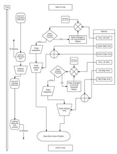
Having the most overhead latency within the loop, the ADC conversion for Up/Down differential input was started first upon entering the loop. The previous Up/Down ADC conversion value is then loaded from memory, scaled to (-127) – (127), and the average noise DC offset is subtracted from the scaled value to fixate the sampled signal to the horizontal axis. The scaled value is then compared to the defined upper/lower thresholds. If the input signal did not break the threshold, its value was used in the running average that was the noise DC offset. The idea was to only average values within the threshold because the mean value would be of all signals we did not consider inputs. If the loaded ADC Up/Down value did break the threshold, our state machine would enter the riemannSum state and add its value to the running area calculation of all super-threshold values sampled. At this point, the program has quantified the input signal, analyzed and determined its significance in our application, and performed the necessary computation to include it in any of our continuously updating variables. The next few operations deal with converting the updated area to coordinates on the screen. This portion of the program was most important for smooth cursor movements and placing the cursor at the exact point our eyes’ are fixated on. But before beginning these operations, the ADC conversion of the Up/Down input was likely completed or at least close to completion. An empty while loop was used to wait for the conversion to complete, if necessary. Following this, the value in ADCH was saved in memory, overwriting the previous Up/Down ADC value used at the beginning of this iteration. ADMUX was then updated to select the input channels connected to the left/right differential signal and MCU ground. The ADC was not immediately restarted because approximately 125 us is needed for the differential gain to stabilize on the MCUs internal op-amp circuitry, otherwise the conversion may be inaccurate. Following a few lines of the code described in the next paragraph, the ADC was started to guarantee a reliable conversion and not increase execution time of the loop despite the channel switching latency.
Our program determines the coordinate our eyes’ were fixated on by using the calibration values found when the device was powered on. To determine the proper calibration value to load from memory, the direction of movement was found by comparing the updated area to its value before the most recent sample was included. If the difference was negative, the eyes were moving downward and oppositely a positive difference indicated the eyes were moving upward. The MCU program then loads the appropriate edge calibration area and divides the current pulse area by it, obtaining the ratio of the eyes’ current angle to the eyes’ angle at the edge. As mentioned earlier, the relationship between the eyes’s angle of deflection and point of fixation on screen is linear within the range of practical angles for this application. Therefore, the product of the eye angle ratio and the number of pixels from the center to the edge of screen our eyes were moving toward will in theory give us the exact pixel from the center our eyes were fixated on. In actual operation this did not move the cursor enough from the center so an additional constant was used to scale up the movement. The calculated vertical pixel position was then saved and the exact same process of normalizing, integrating, and scaling used for vertical movements was done on vertical movements.
The program used the previous ADC conversion on the left/right differential signal that was stored in memory on the previous iteration. Normalizing the value, checking if the input broke the threshold, integrating or averaging the signal, and scaling the area if it was updated required about the same amount of execution time as the vertical coordinate did. With both vertical and horizontal coordinates of the new cursor positions determined, the program first erased the cursor at the old coordinates, converted the new coordinates into fixed point integers, and drew the cursor on the screen using draw_balll, a helper function provided to us in the example TV code used in assignment three. Having completed and included this sample’s contribution to cursor movement, the MCU was only required to wait for the left/right differential input ADC conversion to complete, if it had not already. The value updated in ADCH following the conversion was then stored in memory, overwriting the previous left/right conversion used during this iteration for integrating horizontal signal. The iteration was then complete and waits for the next screen refresh before performing any more computations. This concludes the software component of our final project, but we plan to continue improving the software component to obtain a higher degree of precision and add more functionality to it.
Results
At the time of our final project demo, the eyeMouse was only capable of consistent cursor control in the left/right directions. The user could move the cursor with less than desired precision to specific points on the horizontal axis of the screen but the response time of the cursor movements were less than a tenth of a second. This made the cursor appear to be “glued” to where our eyes were looking.
Using the device for longer than a few minutes proved to introduce accumulated errors and bugs losing control of the cursor all together or giving the user only the ability to spastically race the cursor around the screen. A major cause of this is slight head movements and fluctuations in distance from the screen which would render incorrect areas when scaled with our initial calibration methods. An issue we failed to address due to time constraints was bounding the cursors motions on the edges of the screen. If the user moved their eyes to far across the screen, introducing a pulse with a very high relative area, the resulting horizontal coordinate would be subject to overflow and cause the cursor to reappear on the opposite side of the screen. If this occurred, the accuracy of future cursor movements was unpredictable and the system required a hard reset to return to peak control.
Another issue we encountered was noise introduced into the system from slight movements in the wires connecting the electrodes to the differential amplifier. Many of these movements were involuntary and negligible, but occasionally some of the vibrations could produce noise with an amplitude to break through the sub-threshold region and cause small, but unwanted cursor movement. In order to help mitigate the effects of the noise from movement in the wires, we twister all the wires together. This way, when one of the input wires moved, so did the rest. Because the input was first sent to an instrumentation amplifier with high common mode rejection, this common noise in all of the signals would be attenuated.
We were not able to implement blink filtering and in doing so were not able to implement mouse clicks due to time constraints. However, had we attempted to do so, we would most likely have set some sort of threshold value which, if crossed, indicated the user had blinked. Eye blinks seemed to have a distinct waveform over just simple vertical motion, generally having larger amplitudes. It should be noted that the waveforms in Appendix B discussed later in this section show voltage signals of vertical eye movements and blinks of comparable magnitudes. However, these tests were conducted using the full range of the user’s eye motion. When confined to looking at a computer screen, the magnitude difference between and eye blink and an upward movement would be far more pronounced.
Waveforms
Below are the waveforms for several different eye movements. Each movement started positioned looking straight ahead (center) followed by the series of movements labeled in each caption. Channel 1 was connected to the horizontal electrodes and channel 2 was connected to the vertical electrodes.
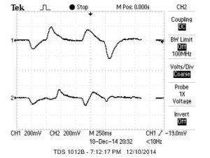
As can be seen from the waveforms, although the exact amplitude of each peak is dependent on the speed at which the user moves his or her eyes, voltage magnitudes around 200 mV were achieved for horizontal movements while peaks of around 400mV were observed for vertical eye movements. It should be noted that purely horizontal eye movements seemed to excite the vertical channel as seen in Figure 12. This could be due to coupling; however, the converse did not appear to be true. In Figure 12, the horizontal channel hardly deviated from its origin when the eye movements were strictly vertical. Another possible explanation could be that the orientation of the vertical electrodes were such that they would actually pick up some horizontal motion. Alternatively, it was very hard for a user to restrict the motion of his eye entirely one access. It is possible that it is harder for a person to move his or her eyes strictly along a horizontal axis. Perhaps people have a natural tendency to look down slightly as they move left and up slightly ad they move to the right. Due to time constraints, we were not able to further explore the origin of these observations. In Figure 14, diagonal movements were examined to see how the channels react when the eye movement is across both axes. The results were as expected. When the user oriented his eyes to the bottom right, the horizontal channel peaked up while the vertical saw a negative peak. As the user’s eyes moved to the upper left, the vertical channel spiked up when the horizontal dropped negative. Finally as the users eyes returned back to center, a smaller peak was seen corresponding to right movement on the horizontal and bottom movement on the vertical. These results were consistent with what was observed in Figure 12 and 13. Finally, Figure 15 shows the waveform when the user blinks. Blinking relates to the act of cleaning one’s eye by rolling it up vertically against the eyelid. The observed waveform was consistent with these motions. The horizontal channel saw no motion when blinking. The blinks triggered a positive peak in the vertical channel followed by a slight negative peak as the eyes moved back down.
Conclusions
The status of our project at the time of our demo did not meet all of our expectations and goals. The results did not meet our expectations because of a few missing functionalities we had hoped to employ within five weeks including clicking, smooth vertical axis control, and the filtering of a few more sources of noise such as head movements. At the conclusion of the five week period, the device we produced had enough functionality to captivate our interests to continue this project on our own time either as an independent study, as a another class project, and even for leisure. Finally starting to see results in the closing days of this semester has only continued our accelerating interest in this idea and we hope to eventually produce a refined and tuned device with enough functionality to publish our results. Although the actual device we built for our final project did not meet all our expectations, the experience of working on our own idea for an extended period of time did not only give us immense satisfaction, increase what we believed we were capable of, and a great time, but also demonstrated the power of working on things you enjoy at a level neither of us had ever seen. We did not see ourselves coming into the lab 8+ hours a day for five or six days a week, let alone enjoying being there the entire time and that’s why we believe the project and everything that went into it blew our expectations out of the water.
In terms of the assignment in ECE 4760, we believe what our project lacked in functionality and user friendliness come demo time was made up for by the complexity and difficulty in our high level design. Past ECE 4760 projects have implemented EOG to control game movements, most notably the EyeSnake Game by Theo Chao and Diane Chang. Their project used the EOG to control the direction of movement of the snake which was moving with a constant velocity. Our own project, attempting to give the user precise control of an object’s movement using EOG, we believe was original and complex enough to at least meet the class standards despite limited functionality.
Lastly, we’d love to actually utilize a set of RF transceivers to enable wireless communication. Because the nRF24L01+ transceivers have given individuals a great deal of noise issues, we plan to obtain RF transceivers with a greater range and more efficient noise reduction to increase the overall quality of this product. By incorporating improved RF transceivers, there is a decreased chance of commands not being received and a possibility of expanding the consumer base to enthusiasts who compete with these vehicles that wouldn’t have been able to do so with the limited range.
The project EyeSnake Game was extremely helpful in the hardware design of our own. The amplification and filtering circuits used in their project were used as a basis for our hardware design, of which we expanded and tinkered with to a large degree. In addition, the circuitry for connecting the LCD TV to the MCU was provided by Bruce Land in an assignment earlier in the semester. On the software side, our project used example code provided to us by Bruce Land for the same assignment. The example code setup all of the protocols, interrupts, and function definitions necessary to draw on the TV allowing us to implement all of our own code within his function main. One of the more exciting elements of our project is with some more progress there may be an opportunity to try and publish our work.
During the five week project we adhered to IEEE code of ethics on all policies. Safety was the first matter of concern because placing any electrical equipment on the head has its risks. Our design isolated all portions of the device powered by a connection to an outlet and we were particularly careful in making alterations to hardware while a person was wearing the electrodes. When our project reached a certain point of progress, we required an individual to wear the electrodes for extended periods of time to allow us both analyze the system’s behavior because progress was much slower with one of us as the test subject. Another exciting portion of our project for us was having our friends, a few of which were not engineers, come to the lab to be a test subject for our eyeMouse. We thoroughly enjoyed explaining many aspects of our design, including everything from EOG to filtering methods in both hardware/software, and were told by our friends seeing our project in various stages was a mind blowing experience. Providing that experience allowed us to adhere to the policy of improving the understanding of technology. Our test subjects watched us apply electrical engineering in ways they had never seen before but with our explanations acquired enough understanding to even ask us questions that made us think.
-
How does the eyeMouse track eye movements?
The device uses electrooculography to measure the electric dipole potential between the cornea and retina, which rotates as the eye moves. -
What is the primary advantage of EOG over infrared methods?
EOG avoids the long-term safety questions regarding illuminating the eye with infrared LEDs. -
Why was a linear optoisolator chosen over a standard one?
A standard optoisolator produced a non-linear output, whereas the IL300 linear optocoupler provided a smooth mapping required for continuous cursor control. -
How does the software calculate cursor position?
The software samples the signal and uses a Riemann sum to calculate the area under the curve, which corresponds to the change in potential and eye angle. -
What safety measures were taken to protect the user?
The design uses a split power supply topology and an optoisolator to ensure no physical connection exists between the user's head and the mains-powered MCU. -
What frequency range do EOG signals typically fall within?
EOG signals from the eye typically fall in the range of 0 to 30 Hz. -
Why was the project scaled down to control a TV instead of a computer mouse?
The team could not establish reliable USB HID communication between the microcontroller and a PC within the time constraints. -
How are DC offsets removed from the signal?
A simple RC high pass filter with a time constant of 1 second is used to remove any DC offset before the signal enters the MCU ADC.