Summary of Fabric-Based Interaction: Unveiling the Conductive Fabric Gesture-Control Sleeve
This project develops a wearable fabric sleeve to reduce smartphone screen reliance by enabling haptic call alerts and gesture control. The sleeve uses a conductive thread capacitive grid for detecting swipes and taps, processed by an Atmel Mega328P microcontroller. Data is transmitted via Bluetooth to a secondary unit controlling an LED matrix or managing phone functions. While achieving 75% accuracy in a lab setting, the system requires further refinement to handle noise in touch sensing algorithms.
Parts used in the Wearable Fabric Sleeve:
- Conductive Thread
- Atmel ATMEGA328P Microcontroller
- HC-05 Bluetooth Module
- Coin Type Vibration Motor
- NPN Transistor (Motor Driver)
- Adafruit Bicolor LED 8x8 Pixel Matrix
- 3.7V Li-Poly Battery
- TPS71933-33DRVR Linear Regulator
- External Resistors (8.2 MOhms and voltage divider resistors)
- Arduino Uno (for testing)
Abstract
This design project addressed the challenges associated with over-reliance on smartphone screens by introducing a wearable fabric sleeve. The sleeve delivers incoming call notifications wirelessly through haptic feedback and enables touch-sensitive gesture recognition for interacting with smartphones or similar devices. The touch-sensitive grid was crafted using conductive thread and relied on high impedance capacitive touch detection. A control unit was implemented to categorize various hand gestures performed on the sensing grid by comparing them against predetermined changes in capacitance and timing thresholds identified through experimentation. Additionally, users received call alerts via a vibration motor, providing tactile feedback. Gesture and incoming call data were transmitted bidirectionally through Bluetooth. While the system functioned effectively in a laboratory environment, achieving over 75% accuracy in gesture classification, the findings suggest that further refinement is necessary to mitigate noise and interference in the capacitive touch sensing algorithm.
1 Introduction
Objective
Over the past decade, advancements in functional textiles have experienced steady growth, resulting in a proliferation of applications for these materials. According to prominent researchers in wearable electronics from The Ohio State University, these textiles are anticipated to continue playing a significant role in various domains such as communication, sensing, and healthcare applications (Gorder). Additionally, intelligent garments have garnered notable interest among professional sports teams and fitness enthusiasts, offering features like health monitoring and activity tracking (Holland). However, few of these fitness-oriented garments have extended their utility beyond these functionalities to cater to the needs of athletes and individuals leading active lifestyles.
Textile applications facilitating music playback and smartphone integration provide users with enhanced device control, representing an initial stride towards integrating connectivity into everyday attire. Consequently, the necessity for such applications serves as the driving force behind our senior design project.
Our objective is to embed gesture control capabilities into a fabric sleeve suitable for athletes and individuals on the move. This sleeve will feature a capacitive touch sensor system crafted from conductive thread on fabric. Its primary function will involve detecting simple gestures, which will then be transmitted via an RF module to a receiver capable of executing corresponding actions based on the gesture pattern.
For this project, the external interface will consist of an LED array setup, mimicking the gestures made by the user on the capacitive grid. Additionally, we aim to incorporate an optional level of complexity, enabling the sleeve to perform basic smartphone functions such as volume control and call management.
Background
Efforts towards creating applications for smart garments have been relatively constrained until now. One notable example is Project Jacquard, a commuter jacket developed by Google and Levi’s, which bears some resemblance to our design. Marketed as a means to keep cyclists connected while on the move, its high price tag ($350) has hindered widespread adoption. In contrast, our sleeve aims to provide a substantially more affordable alternative, while retaining a robust level of functionality and catering to a wider range of users.
High-Level Requirements
– Positioned on the arm, the sleeve will establish wireless connectivity with the phone/LED demonstration subsystem within a range of 0-5 meters.
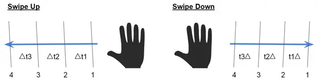
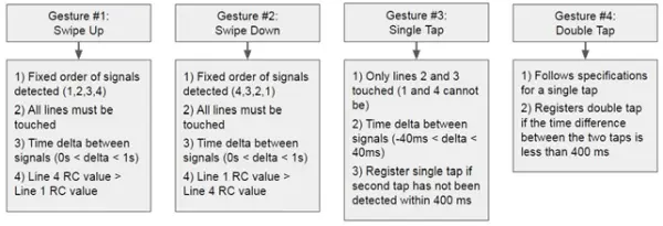
– Capabilities of this system include delivering haptic feedback for incoming call alerts and recognizing four distinct hand gestures on the sleeve: upward swipe, downward swipe, single tap, and double tap. These gestures are illustrated below for clarification:
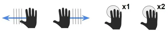
● The sleeve needs to be compact and lightweight, adhering to the subsequent physical specifications:
– Weight: Less than 125 grams.
– Dimensions: Length of Grid – 12-16cm; Width – Less than 35 cm, adjustable by the user.
2 System Design
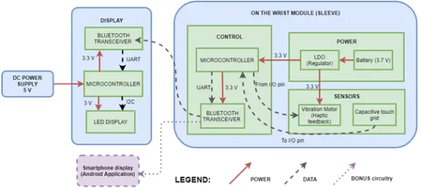
Description of Blocks
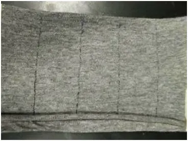
Conductive Thread Capacitive Touch Grid
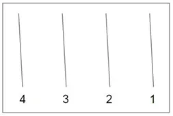
Capacitive touch technology is employed to identify the gestures performed by the cyclist using the sleeve. This technology incorporates a conductive thread pattern and is directly powered by the microcontroller. It is adept at recognizing four distinct gestures: upward swipe, downward swipe, single tap, and double tap. The capacitive grid comprises conductive thread woven into straight lines angled diagonally across the length of the sleeve.
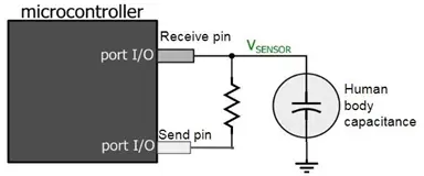
The CapSense Arduino library facilitates the detection of capacitive touch. Within this setup, a solitary I/O pin on the microcontroller serves as the ‘send’ pin, while numerous ‘receive’ pins correspond to each signal line (individual strand of conductive thread). External resistors, each with a value of 8.2 MOhms, are linked between the send pin and every receive pin.
The microcontroller unit (MCU) measures the time taken for the value of the receiving pin to change after the sending pin is set to high. This time duration is influenced by the RC time constant of the circuit, where R represents the 8.2 megaohm resistor. When a ‘receive’ pin is contacted by a human hand, the RC time constant is altered due to the introduction of a dielectric (the human hand). Human body capacitance typically ranges from tens to a couple hundred picofarads. The MCU detects this alteration and signals that the ‘receive’ line has been touched.
This approach will be applied to multiple signal lines, and the MCU will be programmed to differentiate between various gestures (such as swipe up, swipe down, single tap, double tap) based on the signal lines that have been touched.
Microcontrollers
For this endeavor, we opted for the cost-effective Atmel Mega328P microcontroller (MCU) due to its simplicity yet capability to meet our project objectives. It incorporates a standard driver for capacitive touch and offers 23 general I/O pins, adequately accommodating the communication of input and output data between the sensors and the Bluetooth module.
Two MCUs are employed, one on the sleeve subsystem and the other on the LED demonstration subsystem. The MCU embedded in the sleeve subsystem orchestrates the operation of the vibration motor and manages the acquisition and processing of input from the capacitive touch sensor. It gathers data from the conductive threads to discern executed gestures and determine subsequent actions accordingly. Based on the detected gestures, this MCU dispatches output signals to the Bluetooth device. The second MCU is dedicated to supporting the LED display demonstration subsystem. It receives signals from the Bluetooth receiver, deciphering them to determine the LED pattern to be displayed corresponding to the executed gesture.
Bluetooth Module
The bi-directional communication between the sleeve module and the LED array display module is established through the Bluetooth module. Wireless connectivity plays a pivotal role in wearable technology such as this gesture-control sleeve, facilitating communication with other devices and ensuring user accessibility.
For this specific project, the DCD Technologies HC-05 Bluetooth module was selected for various reasons. It supports both slave and master modes, allowing for testing between two MCUs as required for this project. Additionally, the HC-05 devices operate within the specified power requirements of the project (3.3V) and offer a transmission distance exceeding 20 meters, which comfortably meets the project’s needs. Essentially, this Bluetooth device functions as a standard serial COM port.
Alerting Vibration Motor Module
The vibration motor serves to provide tactile feedback, signaling the user of an incoming phone call. As per our project’s timeline, activation of the vibration motor will be triggered by a switch or button prompt. It is affixed to the sleeve module, positioned underneath or inside the user’s forearm to avoid interference with the capacitive touch grid and ensure unobstructed interaction between the motor and the user’s arm. Minimizing the size of the vibration motor was a crucial aspect. Hence, we opted for a coin or “pancake” motor due to its remarkably low profile, measuring approximately 2.6mm.
LED Array Display
The LED module serves to illustrate the responsiveness of the sleeve and reflects the current state corresponding to the gesture pattern. Utilizing a 2D array of LEDs, the user’s gesture on the capacitive touch grid is replicated. For example, executing a downward swipe on the sleeve triggers the LED matrix to simulate colors descending, whereas an upward swipe prompts colors to move in the opposite direction. This module receives its signals from the secondary microcontroller linked to the RF receiver.
The LED array designated for use in this project is a 1.2” Adafruit Bi-Color 8×8 Matrix, featuring 64 Green and 64 Red LEDs. Additionally, the 8×8 matrix will be coupled with a backpack (compatible PCB), which, upon soldering, manages pin multiplexing. Data transmission to the matrix is facilitated through a 2-pin I2C interface.
Power source
The design specifications of wearable devices, characterized by their slim, compact, and lightweight nature, necessitate an advanced power management system equipped with high-power-density batteries to prolong battery life. Several methods can accomplish this, including energy harvesting, rechargeable batteries, wireless charging, and ultra-low power conversion utilizing LDOs.
In the sleeve module, we opted for a 3.7 V, 2000mAh LiPo battery due to its exceptional energy density and slender form factor. Complementing the battery, we incorporated a 3.3 V LDO to facilitate communication with the MCU and other sub-modules.
3 Design Procedure & Verification
Capacitive grid
Testing data for conductive thread
The following data was measured using a Multimeter and conductive thread.
| Length (cm) | Expected Resistance (Ohms)* | Experimental Resistance** (Ohms) | Difference % |
| 5 | 2.625 | 2.3 | 12.38% |
| 10 | 5.250 | 4.1 | 21.9% |
| 15 | 7.875 | 5.5 | 30.16% |
| 20 | 10.5 | 9.3 | 11.43% |
*From datasheet: 0.525 ohms/cm, linear relation between internal resistance and length
**adjusted values taking into account resistance of the multimeter wires
Table 1. Test data on the resistance of the conductive thread at various lengths.
According to the gathered data, noticeable disparities exist in the internal resistance associated with the conductive thread. However, given that this resistance is minimal compared to the pull-up resistor in the ATmega328p, we anticipate no impediment to the RC measurements.
Gesture Timing Threshold Testing
Comprehensive tests were meticulously devised and executed to gather data aimed at discerning thresholds necessary for distinguishing various tap and swipe gestures. Multiple human subjects were engaged to ensure diverse data sets. The primary objective was to accumulate data and conduct time analyses on all anticipated interactions with the capacitive grid. These thresholds will serve to ascertain the spacing between conductive threads and the optimal RC constant.
A straightforward timing analysis was conducted utilizing an accelerometer to track the duration required to execute a hand swipe across a measured distance. The ensuing results and corresponding analysis are detailed below (refer to Figure). Commencing and concluding times were deduced from data points where accelerometer-measured acceleration values equated to zero, indicating the initiation of hand movement (start of swipe) or the cessation of movement (end of swipe).
| Length | # of conductive lines | Distance b/w lines (cm) | Time b/w each line (ms) |
| 14 | 2 | 4.7 | 140.014 |
| 14 | 3 | 3.5 | 106.015 |
| 14 | 4 | 2.8 | 84.008 |
| 14 | 5 | 2.3 | 70.007 |
| 14 | 6 | 2 | 60.006 |
| 14 | 7 | 1.8 | 52.505 |
Table 2. Timing Data for Hand Gestures (Left to Right a.k.a. Swipe Down)
Recognizing two discrete taps as a double tap involves establishing a threshold for the time interval between the two taps. Literature in smartphone application development, such as Swift and Android, suggests that users typically take approximately 0.1 seconds to make contact with their phone screens for a single tap and around 0.2 seconds between discrete taps for a double tap.
However, we found it unreliable to solely rely on these suggested timing thresholds for taps. These recommendations, often subject to developer preferences according to various sources, did not align well with our intended use case, particularly for individuals on-the-go interacting with a sleeve. To address this concern, we conducted our own testing.
The following summarizes the data collected on the duration of double taps:
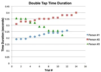
| Person #1 | Person #2 | Person #3 | |
| Average (sec) | 0.223 | 0.354 | 0.298 |
| Min time duration (sec) | 0.190 | 0.310 | 0.224 |
| Max time duration (sec) | 0.259 | 0.400 | 0.355 |
Table 3. Average, min, and max time duration for each human subject.
Utilizing data gathered from 3 human subjects, comprising 37 data points, the mean interval between discrete taps for a double tap is found to be 0.29 seconds, with a range spanning from 0.19 to 0.40 seconds and a tolerance level of +/- 0.1 seconds. The upper boundary of this time interval establishes the criteria for identifying a double tap gesture. Consequently, the outcomes of the double tap testing diverge from the suggested settings outlined in smartphone developer documentation.
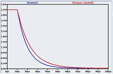
Below, the variances in charge and discharge cycles resulting from alterations in RC time constants are depicted through oscilloscope measurements obtained from the grid:
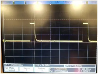
In the diagram provided in Figure 5, the left plot illustrates the voltage pulses observed at the receive pin originating from the send pin. Upon touching the receive pin, the capacitance of the human body elevates the RC time constant of the circuit, as depicted in the plot on the right. Initially, the time duration from peak voltage to the discharge cycle reaching 0V is 13.42 ms. This duration extends to 17.72 ms upon contact with the line.
We also accounted for potential false positives, addressing them through algorithmic methods. These occurrences were largely inconsequential to the physical layout of the grid.
| False Positive Considerations | Solution |
| Prolonged touch (> 1sec) | Do nothing |
| User brushing against lines/grid | Optimal sensitivity to be determined by next steps in testing |
| Grounding | Metal plate skin contact such that user acts as reference point |
Table 4. False Positives in gesture detection.
We also accounted for potential false positives, addressing them through algorithmic methods. These occurrences were largely inconsequential to the physical layout of the grid.
Bluetooth module
To conduct testing, 5V power was provided by the Arduinos. The RX pin of the HC-05 devices was designed to safely function with a 3.3V logic input. While some documentation hinted at the possibility of the RX pins being compatible with 5V operation, practical experimentation revealed that when subjected to 5V, the HC-05 device experienced overheating issues. As a precautionary measure, a voltage divider was constructed using 1x 1k Ohm and 1x 2k Ohm resistors. This divider served to lower the voltage from 5V to 3.3V, thereby offering the board additional protection when connected to a 5V power supply during testing.
The configuration information for each device is shown below:
| Name | Role | Address | CMODE | Default Serial Speed |
| HC-05 Slave | 0 (slave) | 14:3:6446e | 0 | 38400 |
| HC-05 Master | 1 (master) | 14:3:6434e | 0 | 38400 |
Table 5. Configuration information for the master and slave Bluetooth devices.
Vibration motor
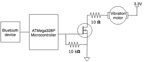
Due to constraints posed by battery size and power, the primary limitation in operating the vibration motor with the MCU stemmed from its demand for high starting and operating currents. Consequently, it became essential to insert a component between the MCU and the motor to ensure safe operation at its specified voltage. An NMOS transistor was selected for this purpose due to its simplicity and versatility.
Power system
When designing the power supply for the sleeve, particular attention was paid to optimizing the power output while utilizing a compact Lithium Ion Battery (3.7 V) capable of producing an output ranging from 3.7 V to 4.2 V when fully charged. LiPo batteries are known for their minimal internal discharge rate, rendering them ideal for applications with low power consumption that require prolonged operation durations.
|
Component |
Part No. |
Voltage (V) |
Typ Current (mA) |
Max Current (mA) |
Power (mW) |
Max Power (mW) |
| Bluetooth module |
HC05 |
2.8 – 3.3 |
35 |
– |
105 |
139.3 |
|
Vibration Motor |
B1034.FL4 5-00-015 |
2.0 – 3.6 |
– |
60 |
120 |
216 |
|
MCU |
ATMega32 8p |
3.3 |
1.7 |
2.5 |
5.1 |
7.5 |
|
LED Array |
Adafruit PI:902 |
3 |
30 |
90 |
||
| Total peak current |
127.5 |
Table 6. Power calculations for sleeve module.
In Table 2 presented above, the subsequent equations were utilized for computing the maximum power consumed by each sub-module:
In the analysis, Ityp was utilized instead of Imax to determine the maximum power required for the Bluetooth module. After considering the current consumption, we opted for a 2000 mAh Li-Po battery, ensuring over 15 hours of continuous operation at peak performance.
The calculation is as follows:
2000 mAh ÷ 127.5 mA = 15.68 hours (assuming maximum current consumption at all times)
Additionally, we employed a Texas Instruments LDO (linear dropout regulator), specifically the TPS71933-33DRVR, to maintain a stable voltage of 3.3 V from the battery. This regulator can deliver up to 200 mA output current, surpassing the requirements of our chips and motor.
During testing with a multimeter, the LiPo battery’s voltage output was measured at 3.82 V initially. However, it gradually decreased over time and would reach a critical voltage level of 3 V upon discharge.
Furthermore, the voltage regulator’s output was examined across various input voltages, consistently providing 3.28 V with a tolerance of ±5%. The MCU (ATMega328p) operated normally at this voltage level.
3.5 LED Array
We developed four routines to showcase the functionality of each performed gesture. This involved utilizing a pre-existing Arduino library for the Max7219 LED Driver and associating gesture values (ranging from 1 to 4) with each routine. To ensure the proper functioning of each routine, we manually transmitted signals representing specific gestures from the Bluetooth slave device to the master.
4 Cost Analysis
| Part | Part Number | Unit Cost | Quantity | Total |
| Conductive Thread | Adafruit Conductive Thread 640 | $9.90 | 1 | $9.90 |
| Microcontroller | Atmel ATMEGA328P-PU | $2.20 | 2 | $4.40 |
| Arduino Uno | – | $0 | 2 | $0 |
| Testing Breadboard | – | $0 | 2 | $0 |
| Various MST / Through-Hole Passive Components | – | $10.00 | – | $10.00 |
| Bluetooth Antennas | DSD TECH HC-05 Bluetooth Modules | $9.99 | 2 | $19.98 |
| LED Array | Adafruit Bicolor LED 8×8 Pixel Matrix | $21.40 | 1 | $21.40 |
| Battery | 3.7V Li-poly batteries | $12.40 | 2 | $24.80 |
| Linear Regulator | TPS71933-33DRVR | $1.67 | 2 | $3.34 |
| Vibration Motor | Coin Type Vibration Motor B1034.FL45-00-015 | $4.94 | 1 package /
5 motors |
$5.95 |
| Vibration Motor Driver | NPN Transistor | $0 | 2 | $0 |
| Total Cost | $99.77 |
Table 7. Component pricing information.
Summary:
● Based on the assumed salary range for B.S. EE graduates during 2014-2015, which is $67,000 annually, the calculated hourly wage would amount to approximately $32.
● Considering the labor costs for one team member over a 10-week development period within a semester, the calculation would be as follows:
($32 / 1 hour) * (10 hours / 1 week) * (10 weeks / semester) * (2.5) = $8,000.
Total Labor Costs: $24,000.
The Total Development Costs encompass both Labor Costs and Component Costs, the latter to be determined, resulting in an approximate total of $24,100 ($24,000 + $99.70 ~ $24,100).
- How does the sleeve detect hand gestures?
The sleeve uses a capacitive touch grid made of conductive thread where the microcontroller measures changes in RC time constants caused by human body capacitance. - What specific gestures can the sleeve recognize?
The system recognizes four distinct gestures: upward swipe, downward swipe, single tap, and double tap. - Can the sleeve provide notifications without looking at a screen?
Yes, the sleeve delivers incoming call alerts wirelessly through a vibration motor that provides tactile feedback. - How far can the sleeve communicate with other devices?
The Bluetooth module supports a transmission distance exceeding 20 meters, meeting the requirement for a 0-5 meter range. - Does the system use standard smartphone timing thresholds for double taps?
No, the team found standard documentation unreliable and established their own threshold of approximately 0.29 seconds based on experimental data. - What power source is used to keep the device lightweight?
A 3.7V, 2000mAh LiPo battery is used due to its high energy density and slim form factor. - Why was an NMOS transistor included in the circuit?
An NMOS transistor was selected to safely drive the vibration motor because the motor demands high starting and operating currents that the MCU cannot supply directly. - How accurate was the gesture classification in the laboratory environment?
The system functioned effectively in a lab environment, achieving over 75% accuracy in gesture classification.