
Summary of TOSHIBA ANNOUNCES NEW PHOTOVOLTAIC-OUTPUT PHOTOCOUPLER
Toshiba Electronics Europe launched the TLP3910, a photovoltaic-output photocoupler in a compact SO6L package (3.84mm × 10mm × 2.1mm). Designed to drive high-voltage power MOSFET gates for galvanically-isolated solid-state relays (SSRs), it offers a minimum open voltage of 14V, eliminating the need for dual-series devices required by previous models like the TLP3906. This single-device solution reduces part count, PCB space, and BOM costs while improving reliability. Enhanced internal discharge circuits achieve a turn-off time of 0.1ms, enabling high-speed operation for industrial and instrumentation applications.
Parts used in the TLP3910 SSR Project:
- TLP3910 photovoltaic-output photocoupler
- High-voltage power MOSFETs
- SO6L package housing
- Galvanically-isolated solid-state relay (SSR) function
- Built-in discharge circuit
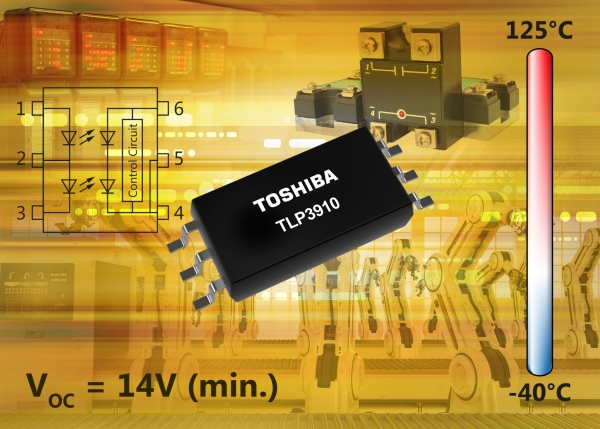
Toshiba Electronics Europe GmbH (“Toshiba”) has launched a new photovoltaic-output photocoupler (“photovoltaic coupler”) housed in a thin SO6L package measuring just 3.84mm × 10mm × 2.1mm, suitable for driving the gates of high-voltage power MOSFETs used to develop a galvanically-isolated solid-state relay (SSR) function.
SSRs are semiconductor relay devices that incorporate a photo-TRIAC, a photo-transistor or a photo-thyristor as the output device. They are generally suitable for applications that require ON/OFF control of large electrical currents such as industrial equipment (I/O relay output for PLCs, inrush current protection in PSUs, battery voltage monitoring in BMS, ground fault detection and more) as well as switching the power and signal lines in instrumentation applications.
A photovoltaic coupler, such as the new TLP3910, is a photorelay that contains the optical elements but not the MOSFET that performs the high-current switching functions. To easily configure an isolated SSR to handle high-voltage, large-current switching (which photorelays find challenging), designers generally combine a photovoltaic coupler with a MOSFET.
Driving a high-voltage power MOSFET with a gate voltage of 10V or higher, currently requires connecting two of Toshiba’s TLP3906 in series, due to the low open voltage that is around 7V. However, the new TLP3910 has a minimum open voltage (VOC) of 14V, double that of the TLP3906 and, as a result, only a single device is required to drive the gate of a high-voltage power MOSFET. This reduces the part count, thereby improving reliability and saving PCB space and BOM cost.
Improvement to the built-in discharge circuit within the TLP3910 has realized a typical turn-off time (toff) of 0.1ms, about one-third that of the TLP3906 and about one-thirtieth that of the TLP191B. The associated typical turn-on time (ton) is 0.3ms and, together, these ensure high speed operation in end applications.
Read more: TOSHIBA ANNOUNCES NEW PHOTOVOLTAIC-OUTPUT PHOTOCOUPLER
- What is the primary function of the new TLP3910 device?
The TLP3910 is designed to drive the gates of high-voltage power MOSFETs to create a galvanically-isolated solid-state relay function. - How does the TLP3910 improve upon the TLP3906 regarding gate drive voltage?
The TLP3910 has a minimum open voltage of 14V, allowing a single device to drive high-voltage MOSFETs compared to the two devices needed for the TLP3906. - What are the physical dimensions of the TLP3910 package?
The device is housed in a thin SO6L package measuring 3.84mm × 10mm × 2.1mm. - Does the TLP3910 offer faster switching speeds than previous models?
Yes, its typical turn-off time is 0.1ms, which is about one-third that of the TLP3906 and one-thirtieth that of the TLP191B. - What benefits result from using a single TLP3910 instead of two TLP3906 devices?
Using a single device reduces the part count, improves reliability, saves PCB space, and lowers BOM cost. - Which applications are suitable for the SSRs developed with this technology?
Applications include industrial equipment I/O relay outputs, inrush current protection, battery voltage monitoring, ground fault detection, and signal line switching. - What is the typical turn-on time for the TLP3910?
The associated typical turn-on time is 0.3ms.
