A little while ago, it struck me that I was getting tired of explaining what FPGAs are and how they work their magic to those of my chums who — thus far — have worked only with microcontrollers (MCUs), so I decided to write a three-part mini-series of articles to offer as an introduction. As I said in the first column:
A lot of my friends are highly experienced embedded design engineers, but they come from a microcontroller (MCU) background, so they often have only a vague idea as to what an FPGA is and what it does. When pressed, they might say something like “You can configure an FPGA to do different things,” but they really have no clue as to what’s inside an FPGA or how one might be used in a design.
The thing is that MCUs are great for some tasks, but not so good at others. When it comes to performing lots of computations in parallel, for example, FPGAs will blow your socks off (so make sure you’re wearing elasticated socks before you start playing with these devices).
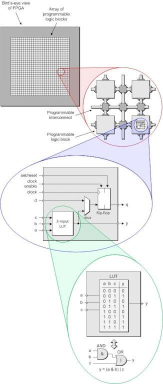
“A picture’s worth a thousand words,” as they say. I agree. I’m a very visual person. Thus, as part of this series, I also created some rather spiffy diagrams, such as the following little rascal:
Now, while the first column focused on the hardware (what’s inside an FPGA), in the second article we turned our attention to the “software.” The reason I put “software” in quotes is that we aren’t talking about a program that runs on a MCU; rather, a language-based description of what we want the functionality of the FPGA to be. I started this second column as follows:
MCU-based designers have typically heard about hardware description languages (HDLs) like Verilog and VHDL; they understand that hardware design engineers use these languages to capture the design intent; but… that’s typically about the extent of their knowledge.
One of the things that MCU guys and gals find it really hard to wrap their brains around is that the languages we use to describe what’s going on inside an FPGA are intended to describe things that happen concurrently, such as the fact that two or more of the device’s inputs may transition at the same time. This is very different to standard programming languages like C/C++, in which things tend to happen sequentially; i.e., one after the other (we’ll ignore multiple threads and multiple processor cores for the purposes if these discussions). Once again, I think my diagrams help to get these concepts over.
Read more: FPGAs For MCU Guys
About The Author
Ibrar Ayyub
I am an experienced technical writer holding a Master's degree in computer science from BZU Multan, Pakistan University. With a background spanning various industries, particularly in home automation and engineering, I have honed my skills in crafting clear and concise content. Proficient in leveraging infographics and diagrams, I strive to simplify complex concepts for readers. My strength lies in thorough research and presenting information in a structured and logical format.
Follow Us:LinkedinTwitter