Summary of How to control LM2596 buck-converter with microcontroller
Summary: The article explains how to adjust a buck converter (like LM2596) output by injecting an external voltage into its feedback pin via a resistor divider. A microcontroller can generate that external voltage using PWM, an RC low-pass filter, and a voltage-follower op amp. Stability of the microcontroller supply is critical because PWM amplitude affects the generated voltage. The article shows calculating the divider resistor when the lower resistor is 330 ohm to scale 5V PWM down to 1.25V, yielding about 990 ohm.
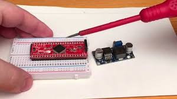
Parts used in the How to control LM2596 buck-converter with microcontroller:
- LM2596 buck converter module
- Voltage divider resistors (example: 330 ohm and ~990 ohm)
- Trimmer resistor (on buck module for manual adjustment)
- Microcontroller (generates PWM)
- RC low-pass filter (to smooth PWM)
- Operational amplifier (configured as voltage follower/buffer)
- Stable power supply for the microcontroller
- Connecting resistors to inject external voltage into feedback pin
Those buck converters will change the output voltage to make the feedback pin, connected to the output via a voltage divider, become 1.25V or so. If feedback is higher, output gets lower and vice versa. If one changes the ratio of resistors in voltage divider, output voltage will change. This is usually done by turning a trimmer resistor with a screwdriver. That is good enough for many applications where voltage will be set only once, but sometimes there is a need to adjust the output voltage more frequently.
External voltage can pull the feedback pin’s voltage higher or lower when applied to it through a resistor. That would make a summer circuit where output voltage of buck converter and external voltage are inputs and output is junction which connects to the feedback pin connects. That external voltage can be generated with just about any microcontroller. Microcontroller generates PWM signal, which is smoothed with RC low pass filter and then buffered with an operational amplifier configured as a voltage follower. Thanks to Hackaday’s Al Williams for pointing this out: I didn’t remember to mention this clearly enough in the video: Circuit shown in this demonstration needs to have really stable power supply for the microcontroller, as the PWM signal’s amplitude depends on the power supply. So any changes on power supply’s voltage will affect the amplitude of the generated voltage and therefore the buck-converter’s output voltage.
In my demonstration the PWM-signal’s maximum voltage and therefore maximum signal generated is 5V. When buck converter’s maximum output is set high enough (lets say 12->V) adjustable resistor’s (which is one between output and feedback) resistance will be relative high compared to the resistance of buck converter module’s fixed resistor (which is 330ohm in this case). Therefore when trying to adjust converter’s output to zero or as low as possible with microcontroller, the output voltage’s effect to voltage on feedback pin will be marginal. Therefore we just need to figure out resistor for voltage divider that divides 5V to 1.25V, where lower resistor is 330 ohm. That is simple task: R = (5V * 330ohm – 1.25V * 330ohm)/1.25V = 990ohm
For more detail: How to control LM2596 buck-converter with microcontroller
- How does the buck converter regulate its output?
The buck converter adjusts output so the feedback pin voltage (via a divider) becomes about 1.25V; if feedback is higher output lowers and vice versa. - Can a microcontroller change the buck converter output?
Yes, by generating an external voltage via PWM, smoothing it with an RC filter, and buffering with an op amp, then applying it to the feedback junction through a resistor. - What components generate the external voltage from the microcontroller?
PWM from the microcontroller, an RC low-pass filter to smooth it, and an operational amplifier configured as a voltage follower to buffer it. - Does the microcontroller power supply matter?
Yes, the microcontroller supply must be really stable because PWM amplitude depends on it and affects the buck converter output. - How do you choose the resistor values for the divider when using 5V PWM and 330 ohm lower resistor?
Calculate the upper resistor so 5V is divided to 1.25V with the lower resistor 330 ohm; the article shows R ≈ 990 ohm. - Why is the adjustable resistor on the module still important?
The module trimmer sets the converter maximum output and affects relative resistor values so the microcontroller can adjust the output range effectively. - What happens if the buck converter maximum output is set much higher than the controlled range?
The adjustable resistor will be relatively high compared to the fixed 330 ohm, making it easier for the microcontroller-injected voltage to adjust the output down to low values. - How is the external voltage applied to the feedback pin?
Through a resistor that forms a summing junction with the converter output divider so the feedback pin sees the summed voltage.