Summary of PWM Motor Driver with MOSFET H-Bridge and AVR ATmega8
This article describes a simple DC motor speed and direction control project using an ATmega8 microcontroller. The system utilizes two PWM channels to drive an RFD3055 MOSFET H-bridge, allowing bidirectional rotation. A toggle switch or wire determines the motor's direction by activating specific PWM outputs, while two push-buttons adjust the speed in fixed increments.
Parts used in the PWM Motor Driver Project:
- ATmega8 Microcontroller
- DC-motor from personal cassette player
- RFD3055 MOSFETs
- H-bridge configuration
- Two-position toggle switch (or connecting wire)
- Push-button S2 (speed increase)
- Push-button S3 (speed decrease)
- 6-pin In-System Programming connector
Here is a very simple project of controlling a small DC-motor (taken from an old personal cassette player) with ATmega8. The ATmega8 is having three PWM channels, out of which two are used here. PWM waveforms are fed to MOSFET (RFD3055) H-bridge. Here, direction is controlled using a two-position toggle switch and speed of the motor is controlled by two push-buttons, one for increasing the speed and other for reducing.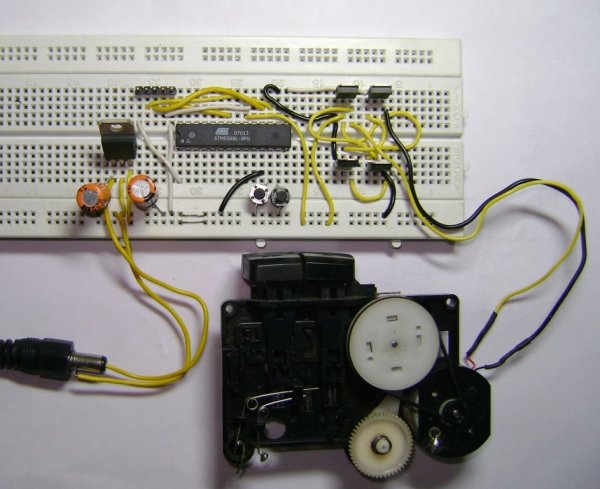
The schematic is geiven here (click on the image to enlarge): When switch SW1 is closed, OC1A channel is active which will feed the PWM signal to Q1 & Q4 MOSFETs. The OC1B pin will remain low keeping the Q3 & Q2 in OFF condition. When SW1 is toggled to open position, OC1A pin will become low, making Q1 & Q4 OFF and OC1B will feed the PWM signal to Q3 & Q2, resulting in the change in the direction of current flow through motor. Hence, motor rotation direction will change. The speed is controlled by Push-buttons S2 & S3. Pressing S2 will increase the speed in fixed steps. Similarly, pressing S3 will reduce the speed in fixed steps. 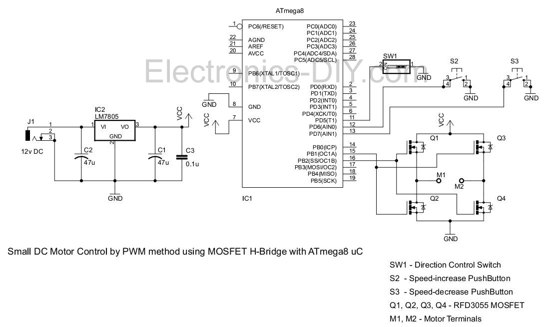
Here on the bread-board, I’ve used two push-buttons but the direction control switch is replaced by a small wire which was connected to ground or kept open for changing the direction (since I was not having the toggle switch in stock at the moment). The bread-board also includes 6-pin In-System Programming connector which is not shown in the schematic.
For more detail: PWM Motor Driver with MOSFET H-Bridge and AVR ATmega8
- How is the motor direction controlled?
Direction is controlled using a two-position toggle switch that toggles between active OC1A and OC1B channels. - What components form the H-bridge in this circuit?
The H-bridge consists of four RFD3055 MOSFETs labeled Q1, Q2, Q3, and Q4. - How does the user increase the motor speed?
Pressing push-button S2 increases the speed in fixed steps. - Which PWM channels are utilized for this project?
Two PWM channels, OC1A and OC1B, are used out of the three available on the ATmega8. - What happens when SW1 is closed?
When SW1 is closed, OC1A feeds the PWM signal to Q1 and Q4 while Q3 and Q2 remain off. - How was the direction switch implemented on the breadboard?
A small wire connected to ground or kept open replaced the toggle switch due to lack of stock. - Can the speed be reduced manually?
Yes, pressing push-button S3 reduces the speed in fixed steps.