Summary of Variable Power Supply with LCD
This article details building an adjustable LM317 power supply with a digital voltage display. It combines a standard linear regulator circuit with an ATmega16 microcontroller to measure and show output voltage on an LCD. The design includes a voltage divider to safely scale high input voltages down to the microcontroller's 5V limit, ensuring accurate readings without damaging the controller.
Parts used in Adjustable Power Supply with Digital Display:
- LM317 IC
- Resistor – 240 Ohms
- Capacitors – 0.1uF, 10uF
- Potentiometer – 5k
- 30V/1A Adapter (or transformer + Bridge wave rectifier IC)
- ATMega16 Developments Board
- 16 x 2 LCD Board
Are you an electronic hobbyist? Then an adjustable power supply is a must for your various needs. This project explains how to make a LM317 based adjustable power supply unit with a digital display.
Components Required
1. LM317 IC
2. Resistor – 240 Ohms
3. Capacitors – 0.1uF, 10uF
4. Potentiometer – 5k
5. 30V/1A Adapter (or a transformer + Bridge wave rectifier IC)
6. ATMega16 Developments Board
7. 16 x 2 LCD Board
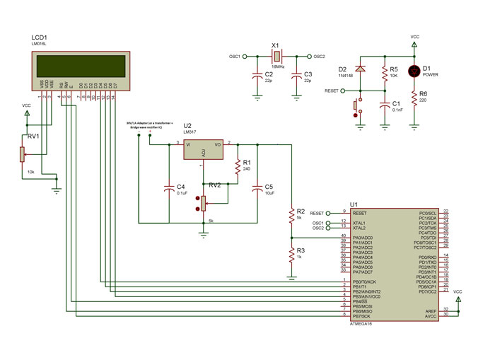
Circuit Design
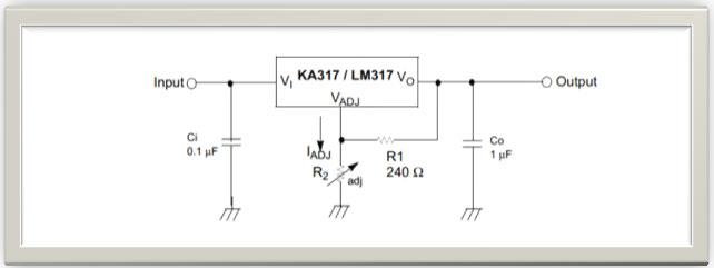
Well the power supply circuit is very simple and can be found in the datasheet of LM317 itself.
What we need to design is the additional voltmeter kind of arrangements using a microcontroller in order to display the output voltage value accurately. For this, we use the ADC feature of the microcontroller.
But the problem is that ATmega16 can only take up to 5V. Input voltage more than that can fry up the controller.
Solution: A Voltage divider circuit!
Here R1 and R2 are the resistors and Vin is the input voltage. The output voltage Vout is given as:
Vout = Vin X R2/(R1 + R2) . . . . . . . . . . . . . . . (1)
We choose the resistor values based on our requirements. Like say now our maximum voltage to be measured is 30V but we can only give up to 5V to our controller.
For more detail: Variable Power Supply with LCD
- What components are required for this project?
The project requires an LM317 IC, 240 Ohm resistor, 0.1uF and 10uF capacitors, a 5k potentiometer, a 30V/1A adapter or transformer with bridge rectifier, an ATMega16 board, and a 16 x 2 LCD board. - How does the microcontroller display the output voltage?
The system uses the ADC feature of the microcontroller to create a voltmeter arrangement that displays the output voltage value accurately. - Why is a voltage divider circuit necessary?
A voltage divider is needed because the ATmega16 can only accept up to 5V; without it, higher input voltages would fry the controller. - What formula determines the voltage divider output?
The output voltage Vout is calculated using the formula: Vout = Vin X R2/(R1 + R2). - Can you use a transformer instead of an adapter?
Yes, you can use a transformer combined with a Bridge wave rectifier IC as an alternative to the 30V/1A adapter. - What is the maximum voltage the microcontroller can handle directly?
The ATmega16 microcontroller can only take up to 5V directly. - Where can I find the basic power supply circuit design?
The basic power supply circuit design is found in the datasheet of the LM317 itself.