Summary of Frequency counter circuit
Simple Frequency Counter Summary: This project uses an AVR Atmega8 timer/counter to count input signal pulses for one second and displays the result on an LCD, giving a simple frequency meter. A conditioned square or pulse signal is recommended; signal conditioning (comparator, Schmitt trigger, sine-to-square) may be used. The included Embedded C code zeroes TCNT1, waits 1 second (adjustable by SMP), reads TCNT1 into an unsigned int, and prints the frequency on the LCD.
Parts used in the Simple Frequency Counter:
- Atmega8 microcontroller (AVR)
- LCD display
- Signal source (input signal to be measured)
- Signal conditioning circuit (optional): Comparator
- Signal conditioning circuit (optional): Schmitt trigger
- Signal conditioning circuit (optional): Sine wave to square wave converter
- Power supply (suitable for Atmega8 and LCD)
- Wiring/PCB or breadboard and connectors
Simple Frequency Counter
You may have already seen various projects over many websites named Frequency counter, Digital Frequency Counter etc. I’m posting just another of them. Showing the use of timer/counter of AVR micro controller (Atmega8) in one of it’s form. This circuit can be used as a simple micro controller project for your engineering courses. Frequency of a periodic signal is the number of cycles it repeats per second! So If we count the number of cycles recorded in a second it will directly read the frequency. So what we are going to make is a frequency counter circuit, which can also be called as a frequency meter.
To make this frequency meter 1) we need a signal (whose frequency has to be counted) 2) Atmega8 micro controller from Avr 3) An LCD to display the counted frequency. I assume that you are familiar with Avr Atmega8 and you know how to program it. You also need to know – How to interface LCD with Avr
Now let’s get into the details of the project – Simple Frequency Counter or otherwise Frequency Meter!
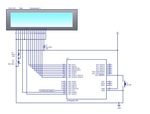
Take a look at the circuit diagram given below and also skim through the program given towards the end of this article.
Description of circuit:-
So what I have done here is; Set the counter to zero, waited for 1S, and read the counter again. But remember,you need to read the value immediately after the delay loop ends. It is simple. Just assign a variable and copy the count to that. The data type of the variable is essentially an unsigned integer. You can try floating point data type too! But here you need to typecast it! That’s all! To read about floating point conversion in Avr – read this article carefully – String Formatting of Avr
And yes! It’s better that you apply a conditioned signal for counting the frequency. i.e. a square wave or a trail of pulses. You may use a suitable signal conditioning circuit like Comparator; Schmitt trigger, sine wave to square wave converter, whatever suits you. If the signal is of low power, then use a conditioning circuit . You can get lots of signal conditioning circuits in this website – check here – Signal Conditioner Circuits
Now here is the Technical details of my project. I hope you’ll have not much problem to make this.
The program [Embedded C, AVR Studio]:
#define F_CPU 1000000

#include

#define SMP 1
int main(void)
{ unsigned int i;
stdout=&lcd_str;
initLCD();
_delay_ms(50);
while(1)
{ TCNT1 =0;
_delay_ms(1000/SMP);
i=TCNT1;
LCDcmd(0x01);
printf(“Freq:%uHz”,i*SMP);
_delay_ms(500);
}
return 0;
}
Read more: Frequency counter circuit
- What microcontroller is used in this frequency counter?
Atmega8 AVR microcontroller is used. - How does the circuit measure frequency?
It clears the timer TCNT1, waits one second, reads TCNT1, and displays the count as frequency. - Can the display show the measured frequency?
Yes, the counted frequency is printed to an LCD using printf routed to the LCD. - Do I need signal conditioning for the input?
It is recommended to apply a conditioned signal such as a square wave or use a signal conditioning circuit if the input is low power or not square. - What conditioning circuits are suggested?
Comparator, Schmitt trigger, or a sine wave to square wave converter are suggested. - How is the counting interval controlled in the code?
The code uses _delay_ms(1000/SMP) where SMP can be set to adjust the counting interval; SMP is defined as 1 in the example. - What data type stores the counted pulses?
An unsigned int variable is used to store the TCNT1 count. - Is floating point required to compute the frequency?
No, the example uses integer arithmetic; floating point can be used but would require typecasting and formatting.