Summary of GETTING STARTED WITH AVR MICROCONTROLLER
This article introduces the AVR microcontroller, focusing on the ATmega32 model. It covers its history, architecture, key features like flash memory and ADC channels, pin configurations, and programming using AVR Studio. The text details how to set up projects, compile code, and utilize various interfaces such as SPI, USART, and TWI for applications ranging from sensor interfacing to motor control.
Parts used in the AVR Microcontroller Project:
- AVR Microcontroller (ATmega32)
- External Crystal Oscillator (16MHz)
- Capacitors (22pF)
- AVR Studio Software
- AVRISP Programmer
- AVRISP2 Programmer
- LCD Display Interface
- Sensors and Transducers
- GSM Module
- GPS Module
GETTING STARTED WITH AVR MICROCONTROLLER.This article will make you familiar how to getting started with AVR Microcontroller. You will learn each and every thing about AVR microcontroller. What are the basic features of AVR microcontroller, Architecture of AVR microcontroller? Here you will also learn about the programming strategy of AVR microcontroller & basic introduction of software AVR Studio.
WHAT IS AVR MICROCONTROLLER?
AVR microcontroller is an advanced version minicomputer integrated on a small chip having a processor, memory and programmable input/output peripherals. The main function of AVR microcontroller is to provide a digital control over any type of system (electrical, mechanical or automotive), different devices, industrial plants and most of electronic gadgets and appliances. AVR microcontroller is the first on chip flash memory comes in 8-bit, 16-bit, 32-bit integrated chips.
HISTORY OF AVR MICROCONTROLLER
After PIC microcontrollers AVR microcontroller being advanced and sophisticated microcontroller was developed by ATMEL in 1996, its architecture was first envisage by two students Alf-Egil Bogen and Vegard Wollan at Norwegian institute of technology that’s why the term AVR stands for Alf-Egil Bogen and Vegard Wollan’s RICS (reduced instruction set computing) microcontroller. AVR microcontrollers are divided into following groups:
- Classic AVR (AT90SXXXX)
- Tiny AVR (ATtinyXXXX)
- Mega AVR (ATmegaXXXX)
- Xmega AVR (ATXmegaXXXX)
- Application-specific AVR
- 32-bit AVR
FEATURES OF AVR MICROCONTROLLER ATMEGA32
Lets starts with the Atmega32 IC its basic features are:
- 32K Bytes of flash memory
- 1024 Bytes EEPROM
- 2K Byte of SRAM
- 8 channels, each f 10-bits ADC
- 32 general purpose I/O lines and registers
- JTAG interface
- Internal & external interrupts
- Serial programmable USART
- TWI interface
- 4 PWM channels
- SPI serial port
- Operating voltages: 4.5 V – 5.5 V
- Operating frequency: 16MHz
ARCHITECTURE OF AVR ATMEGA32
AVR Atmega32 is low power, efficient and high performance integrated chip comprises of advanced virtual RISC architecture. It can interpret 6millions instructions per seconds (MIPS). AVR Atmega32 is a 40 pin integrated chip in which 32 pins are input/output pins in the form of four ports; PORTA, PORTB, PORTC & PORTD and other are voltage supply, ground, analog reference, crystal & reset pins. Each port provides bi-directional I/O interface, comprises of 8 pins in which each pin is 8-bits wide.
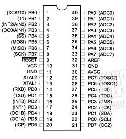
The RESET pin is an active low pin which activates when a low voltage (0 volts) is applied; it causes the microcontroller to starts from its default (initial) mode/state. Almost all the signals form environment are analog signals but microcontrollers understands only digital language that’s why form analog to digital conversion PORTA is used, comprises of pins from A0 to A7also known as ADC pins. AREF pin is an analog reference pin used for ADC & VACC pin is a voltage supply also used for ADC. There are two ground (GND) pins used to provide ground to AVR microcontroller.
VCC is the main supply of AVR Atmega32 which is 5 volts DC. The operating frequency of AVR Atmega32 is 16MHz, for this an external crystal oscillator of 16MHz is connected to XTAL1 & XTAL2 pins along with 22pF capacitors, where XTAL1 is used for providing input to the inverting clock oscillator and internal clock operating circuit while XTAL2 is the output from the inverting oscillator amplifier. AVR also have TWI (two wire interface), JTAG (joint test action group) interface and in system programmer (ISP) serial peripheral interface (SPI). JTAG is used to provide access to its internal memory and register. With the help of this feature we can perform single-stepping execution and setting break points in code.
Following table will helps you while understanding functions of each and every pin.
| PIN NO. | PIN NAME | PIN FUNCTIONS |
| 1 | XCK/T0/PBO | T0 -Timer 0 external counter input or XCK- USART clock I/O or PB0-I/O pin 0 of PORTB |
| 2 | PB1/T1 | Timer 1 external counter input or I/O pin 1 of PORTB |
| 3 | PB2/INT2/AIN0 | PB2-I/O pin 2 of PORTB or INT2-external interrupt 2 or
AIN0-analog comparator |
| 4 | PB3/OC0/AIN1 | PB3-I/O pin 3 of PORTB or OC0-timer0 output or
AIN1-analog comparator |
| 5 | PB4/SS | I/O pin 4 of PORTB or ISP & SPI |
| 6 | PB5/MOSI | I/O pin 5 of PORTB or ISP & SPI |
| 7 | PB6/MISO | I/O pin 6 of PORTB or ISP & SPI |
| 8 | PB7/SCK | I/O pin 7 of PORTB or ISP & SPI |
| 9 | RESET | active low, RESET pin |
| 10 | VCC | Main supply (5 volts DC) |
| 11 | GND | Ground |
| 12 | XTAL1 | for providing input to the inverting clock oscillator and internal clock operating circuit |
| 13 | XTAL2 | output from the inverting oscillator amplifier |
| 14 | PD0/RXD | I/O pin 0 of PORTD or USART serial communication interface |
| 15 | PD1/TXD | I/O pin 1 of PORTD or USART serial communication interface |
| 16 | PD2/INT0 | I/O pin 2 of PORTD or external interrupt 0 |
| 17 | PD3/INT1 | I/O pin 3 of PORTD or external interrupt 1 |
| 18 | PD4/OC1B | I/O pin 4 of PORTD or PWM channel |
| 19 | PD5/OC1A | I/O pin 5 of PORTD or PWM channel |
| 20 | PD6/OCIB | I/O pin 6 of PORTD or timer/counter 1 input |
| 21 | PD7/ICP1 | I/O pin 7 of PORTD or timer/counter 2 output |
| 22 | PC0/SCL | I/O pin 0 of PORTC or TWI interface |
| 23 | PC1/SDA | I/O pin 1 of PORTC or TWI interface |
| 24 | PC2/TCK | I/O pin 2 of PORTC or JTAG interface |
| 25 | PC3/TMS | I/O pin 3 of PORTC or JTAG interface |
| 26 | PC4/TD0 | I/O pin 4 of PORTC or JTAG interface |
| 27 | PC5/TDI | I/O pin 5 of PORTC or JTAG interface |
| 28 | PC6/TOSC1 | I/O pin 6 of PORTC or timer oscillator pin1 |
| 29 | PC7/TOSC2 | I/O pin 7 of PORTC or timer oscillator pin2 |
| 30 | AVCC | voltage supply for ADC |
| 31 | GND | Ground |
| 32 | AREF | analog reference pin for ADC |
| 33-40 | PA0/ADC0 – PA7/ADC7 | I/O PORTA or 8 channel, 10-bit wide ADC |
PROGRAMMING STRATEGY OF AVR ATMEGA32
The AVR Atmega32 is a programmable integrated chip that’s why it is necessary to program AVR to operate it for required applications. For the programming of AVR microcontroller the simplest way is to use AVR STUDIO.
AVR STUDIO
AVR Studio (with different versions) is an integrated development environment by ATMEL to develop different applications as per requirements. We can use C language or assembly language to built-up codes for AVR microcontrollers.
To built-up project on AVR Studio follow the steps below:
- First opens the AVR Studio and selects the new project option.
- Enter project name and select AVR GCC, enter location then click next.
- Select your debug platform (AVR simulator) and required device (AtmegaXX) and click finish.
- A window will open, click project button and go to configuration option, select your required options and click OK.
- Write your required code in main window.
- For compilation select the build button and go to compile option. In case of error compiling will fail.
After the generation of HEX file store the program into AVR microcontroller. For this you have to dump the HEX file into AVR by using programmer. The common programmers used for AVR microcontroller is AVRISP and AVRISP2.
APPLICATIONS OF AVR MICROCONTROLLER
AVR microcontroller can be used for any type of project applications such as:
- For signal sensing
- Data acquisition
- Motion control
- To interface motors
- For displays on LCD
- To interface any type of sensors and transducers
- To interface GSM and GPS
- To control and automize industrial plants, mechanical & electrical systems
- To automize heavy machineries
- For developments for UAVs (unmanned aerial vehicles)
In next tutorial you will learn about AVR studio 6 and how to create your first project using AVR studio 6. For more information keep visiting our blog.
Source: GETTING STARTED WITH AVR MICROCONTROLLER
- What is an AVR microcontroller?
It is an advanced minicomputer integrated on a small chip containing a processor, memory, and programmable input/output peripherals for digital control. - How does the RESET pin function on the ATmega32?
The RESET pin is active low; applying 0 volts causes the microcontroller to start from its default initial mode. - What components are required for the operating frequency of 16MHz?
An external crystal oscillator of 16MHz connected to XTAL1 and XTAL2 pins along with two 22pF capacitors is required. - Can I use C language or assembly language for programming?
Yes, you can use either C language or assembly language to build codes for AVR microcontrollers within AVR Studio. - Which programmers are commonly used to dump HEX files into the microcontroller?
The common programmers used are AVRISP and AVRISP2. - What is the purpose of the AREF pin?
The AREF pin is an analog reference pin used specifically for Analog-to-Digital Conversion (ADC). - Does the ATmega32 have JTAG interface capabilities?
Yes, it has a JTAG interface used to provide access to internal memory and registers for single-stepping execution and setting breakpoints. - What are some application areas for this microcontroller?
Applications include signal sensing, data acquisition, motion control, LCD displays, GSM/GPS interfacing, and industrial automation.