Summary of Gimmick on Barebones Arduino 16MHz
This article details a method to build a compact 16MHz barebones Arduino without external load capacitors by creating them from copper tape and Kapton insulator. The project utilizes the internal ground plane of the microcontroller and custom-woven capacitors to achieve stable clock speeds while minimizing component count.
Parts used in the Barebones Arduino 16MHz:
- Atmega328P microcontroller
- ABL-16.000MHZ-B2 crystal
- Copper tape (0.25 inches wide)
- Kapton tape
- Exacto knife with new blade
Story
Did you see this 8MHz no-crystal Arduino?
Arduino on Internal Oscillator Crystal as Clock Source by Naman Chauhan is a great project if you can live with 8MHz using the internal RC oscillator of the Atmega328P chip. I really like Naman’s project; I did my own version of the 8MHz Arduino many years ago here on Hackster. The 8MHz version conserves power, is Arduino IDE friendly, and is as cheap as the raw Atmel chip.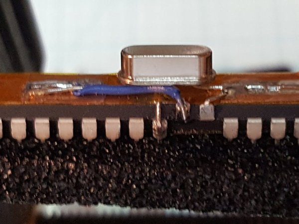
But what if you need a 16MHz Crystal Stabilized barebones?
Silly me, there must be a thousand projects out on the Internet about building your own Arduino from bare parts. Heck, I even did one back a while here on Hackster. But can I make it more bare and still run at 16MHz? You bet your chips I can!
One of the more annoying things about crystal-controlled micro-controllers is that the crystal circuitry employs something known as load capacitors. (Not true for circuits built with a ceramic resonator as the resonator has manufactured capacitance within the unit.) With the Arduino barebone circuits, two small load capacitors of values from 12pF to 22pF are usually specified and the value is based upon the specific crystal manufacturing process. Specific values are therefore in the manufacturer’s datasheet. Adafruit has a rather nice write-up on the subject if you require more information.
If I could just throw away everything except the crystal, then I am only 1 component over that used in Naman’s project with a total of just 2 parts: uC and crystal. Are the load caps not required? Yes, but we can actually make ’em right into the project with a little hacking. Remember, electronics and physics are eternally linked.
The process to build a small capacitor is not unlike what was done back in 1745 when the Leyden Jar was created. Except in our case, our little capacitor (we will need 2 identical ones) will be just 7.10 mm wide and between 10.0 and 13.0 mm long. Instead of glass, we are going to use a marvelous tape known as Kapton selected for the high temperature thermal stability of the product.
Steps
We are going to create a ground plane across the entire top of the IC which is 35.0 mm. I used an exacto knife with a new blade to cut a strip of copper tape to fit the top of the IC in length. The width of the cut tape was 0.25 inches.
Now that we have a ground plane, we need to reference it to the chip’s ground pins (Note: If your need require separate analog and digital ground planes, leave the analog ground un-soldered to the copper tape.)
Just like a Leyden jar, we will need an insulator, so our Kapton tape needs to be cut to width (must be a wee bit wider than the copper tape ground-plane), and the length needs to wrap around the bottom of the chip and overlap. Keep the tape smooth on the top-side of the chip so that it and the copper are smoothly bonded without bubbles.
At this time we have 2 component parts of the capacitor, one contact and the insulating material. To complete, we need our second electrical contact. This will again be a strip of quarter-inch wide copper tape and the length of the strip will determine the capacitance. 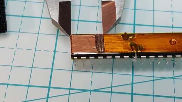
Capacitance
In the above picture, the value read by my capacitance meter is 18 pF. The table below shows the capacitance from longer lengths:
- 13 mm == 27 pF
- 12 mm == 24 pF
- 11 mm == 21 pF
- 10 mm == 18 pF
Two capacitors formed by the tape and common ground plane will provides our two load capacitors for the 16 MHz crystal. You can elect to use a different mounting strategy for the crystal, but I elected to use what I thought was the simplest and most electrically stable. This mounting required the two Xtal pins on the uC to be bent upwards: XTL1 being connected to one pad and XTL2 being connected to the other. The ABL-16.000MHZ-B2 crystal is joined by soldering the outwardly bent leads.
For more detail: Gimmick on Barebones Arduino 16MHz
- Why are load capacitors usually required for crystals?
Load capacitors are typically needed because crystal circuitry requires specific capacitance values based on the manufacturing process to stabilize the frequency. - How can I create load capacitors without buying separate components?
You can construct two identical capacitors using strips of copper tape and Kapton insulating tape wrapped around the microcontroller chip. - What material is recommended for the insulator in this project?
Kapton tape is selected for its high temperature thermal stability to serve as the insulator between the copper layers. - How does the length of the copper tape affect the capacitor value?
The capacitance increases with the length of the copper strip, ranging from 18 pF at 10 mm to 27 pF at 13 mm. - Can I use ceramic resonators instead of crystals for this setup?
No, the text notes that ceramic resonators have manufactured capacitance within the unit and do not require external load capacitors like crystals do. - How should the XTAL pins be prepared for mounting the crystal?
The two Xtal pins on the microcontroller must be bent upwards so they connect to the pads where the crystal leads are soldered. - Is it possible to separate analog and digital grounds in this design?
Yes, if separate grounds are required, the analog ground should be left unsoldered to the copper tape ground plane. - What is the total number of main components used in this minimal project?
The project uses only two main parts: the microcontroller and the crystal, with the capacitors being fabricated from tape.