This project develops a GPS navigation device enabling off-road path following via user-defined waypoints, ideal for skiing and biking. It features two modes: Navigator Mode for guiding users along pre-plotted paths using visual and LED turn indicators, and Exploration Mode for logging custom routes. The system utilizes a microcontroller to process GPS data, calculate headings, and communicate with a computer via UART to visualize tracks on mapping websites like GPS Visualizer.
- Adafruit Ultimate GPS Breakout
- ATmega1284p Microcontroller
- LCD Display
- Pushbutton
- Potentiometer
- Three LEDs (two for navigation, one for debugging)
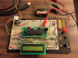
- Breadboard
- Limiting Resistors
- USB Computer Connection
The idea of the the project is to create a useful device for being able to get directions with any specified path by use of waypoints rather than a path chosen by a GPS as well as being able to follow a path that is offroad. The basis of this project was to provide a way to ski down an unfamiliar mountain without making a wrong turn by loading the path on the device, as well as plotting a new path to be able to view the path later. Note that this also works very well for biking where one may want to choose their own path and ride specific roads rather than going on the shortest path. A normal GPS is able to provide functionality on roads, but not off-road where the paths are not already mapped, so this device is quite beneficial for skiing and snowboarding in particular.
High Level Design
Overview
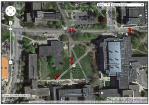
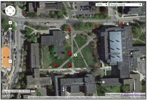
The basis for creating this functionality relies on a GPS to track location at different instances of time. The process of creating a path to follow at a later time is as follows. First, on a website similar to gpsvisualizer.com, you are able to view maps like Google Maps and additionally add markers to indicate waypoints and download the path in a standardized file format (gpx). To create the path, you put waypoints at every place there should be a turn. Additionally, at each waypoint, a second waypoint closeby is used to create a vector, to be used later while following the saved path. Then, we parse the output of Google Maps to take the waypoints and convert them into waypoint locations and vectors at each waypoint. After loading the path on the device and starting the sequence, the skier (for example) will begin going down the slope. Before the waypoints, the GPS will determine the person’s location and heading. Then, once the skier is close enough to the next waypoint, the LCD will display the direction one should turn as. Additionally, 2 LEDs will flash (one for left, one for right) a number of times to represent the degree angle one should turn to display turn information at a glance.
For logging, rather than inputting a path, the device will save the GPS locations every time the user presses a button. The device will store all this information in the microcontroller. Later, at a computer, one can connect the device to the computer using UART and send the coordinates to the computer where it is copied from UART to a text file. Then, after parsing the output, you can upload the file to GPS Visualizer to view the path.
Psuedocode of program
Navigator Mode
map = Google_maps.insert(waypoints) // insert waypoints on Google maps

points = Parser.extract(map) // extract Google maps waypoints to txt file

Loader.transfer(points, MCU) // transfer points to microcontroller

while( MCU.execute(points) ) { // waypoint control for each point

update_heading(location,prevlocation) // update heading in relation to past location if travel far enough    if (location.iscloseto(waypoint)) { // execute only if close to the next waypoint

MCU.blink_led(location, position) // blink based on waypoint, position

}

}
Exploration Mode
while( MCU.running() ) { // while GPS is running

if ( MCU.istakingTurn() ) { // execute only GPS appears to be turning

MCU.send(vibration, MCU2) // send the vibration to any listening MCUs

MCU.log(location) // add GPS waypoint

}

} MCU.transfer(log, Loader) // transfer GPS log to computer
Block Diagram
Hardware and Software Tradeoffs
There were several tradeoffs for the hardware and software used in the project. First, in software, because of the limited power of the microcontroller, some calculations were approximated in order to minimize the number of cycles used. For distance, rather than using the distance formula of two multiplications, and summation, and a square root to calculate distance, we instead use a comparison to thresholds of latitude and longitude independently. Additionally, rather than using every GPS datapoint that is sent to the MCU, the microcontroller only computes data every 0.2 seconds. These approximations don’t degrade any noticeable difference to the performance of the device, but save in terms of power and cycles on the microcontroller.
For hardware, we tried to minimize the amount of peripherals needed on the device by squeezing all interactions of the user interface into a single button and potentiometer. By doing so, we were able to remove a large number of buttons the could have been used to change menus and instead use the potentiometer to scroll between all the menus. By minimizing the amount of hardware, we streamline the amount of extra hardware and extra inputs onto the microcontroller. Also, mostly due to the time constraint, we do not have the full GPS device neatly packaged into a small, enclosed, water-proof case. This would be necessary for a fully-functioning device, especially for its use during snowboarding, but due to time, we instead created the device on a breadboard and did not attempt to package the device.
Standards
GPX
The GPS coordinates are plotted using a standard xml format with the file extension “gpx”. This file extension specifies the order and waypoint latitudes and longitudes. The coordinates are readily downloaded off of any GPS plotting system (such as gpsvisualizer.com) and then inserted into our parsing script to put on the microcontroller. After the microcontroller has transferred its coordinates captured in exploration mode, the coordinates are sent to the computer using UART. Again, a script converts these coordinates to the gpx standard file format, so that any GPS visualization software may be used.
NMEA
To transfer GPS coordinate data between the GPS module and the microcontroller, the standard NMEA messaging system is used. The most pertinent of these message types is GPRMC. When this message type is received by the MCU, the data fields in this message can be used to extract the current GPS coordinates.
UART
To communicate between the computer, microcontroller, and the GPS module, a UART system is used. Messages are sent and received based on the protocol timings and behavior that is required of all UART communication.
Existing Work
After the project conception and execution, numerous projects were found that used microcontrollers to provide navigation. One such example is the Cornell ECE4760 project by J. Heck and K. Kulas, that uses similar ideas to guide people using vibration. However, our method of inputting headings has not been found to be used by any other project.
Hardware
Hardware Design
GPS Unit
The core of navigation device is the GPS unit. Using the Adafruit GPS unit, we are able to gather location data, compare locations, and determine how the user should proceed in their movements. This project uses a GPS unit from Adafruit that uses a UART interface to communicate with other devices. Using the standard NMEA GPS messages, we are able to both control the data that the GPS unit sends to MCU as well as understand the GPS coordinates that are sent to the MCU. The GPS unit is powered off of the MCU’s 5V power source, and is connected to the USART0 transmit and receiving pins on the ATmega1284p.
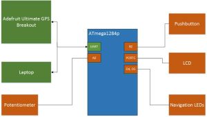
Device Communication
There are three functional units that must communicate with each other: the laptop, ATmega1284p, and the Adafruit Ultimate GPS Breakout. The communication between the Adafruit GPS unit and the ATmega1284p microcontroller is using a UART transmit/receive protocol. The ATmega1284p and laptop must communicate in order to relay data. To send the waypoints for navigation, one utilizes the output script’s header file and the data is transferred when the microcontroller is programmed. The waypoints that are triggered in exploration mode are sent back to one’s laptop using a UART channel. This hardware utilizes UART transmit/receive wires to a USB computer connection.
LED Output
There are three LEDs on the device board that provide information to the user. Two of these LEDs are used notify the user when to take a turn during navigation mode. The LED on the microcontroller board is used for debugging information: the LED toggles when the button is pushed in exploration mode, and the LED toggles when a minimum distance has been walked during navigation mode. Each LED is powered when on by an output pin on the MCU. The circuit starts from the MCU output pin, through a limiting resistor, through the LED, and to circuit ground.
User Interface: LCD Output
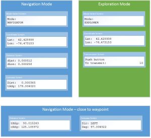
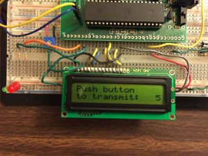
The user interface is through an LCD output that prints statistics and menus for the user. There are two modes: exploration mode and navigation mode. In the exploration mode, there are three screens that may be accessed: a mode-select screen to change to navigation mode, a screen showing the current GPS coordinates, and a screen where the captured waypoints can be transmitted to the computer.
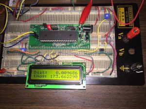
In navigation mode, there are four screens: a mode-select screen to change to exploration mode, a screen showing the current GPS coordinates, “distance screen,” and “compass screen.” The distance screen shows your distance away from the next waypoint in fractional degrees for both latitude and longitude. When the user is sufficiently close to the next waypoint, the “distance screen” changes to display your current heading and target heading (the heading you should use at the next waypoint). Headings are given in typical heading degrees, where 0 is due north and 90 is due east. In the “compass screen,” the LCD displays the distance away from their next waypoint and the heading the user must travel to go to that waypoint. At a sufficiently close distance to the waypoint, the device will display which direction the user must travel as a turn at the waypoint (either LEFT or RIGHT), as well as the bearing (90.0 for a 90 degree turn).
The LCD is controlled by the MCU using seven wires that connect to an output port on the MCU. The LCD is powered on the MCU’s 5V power supply. There is also a brightness control for the LCD using a potentiometer.
There are two pieces of hardware provided to the user to interface with the navigation device: a pushbutton and a potentiometer. The potentiometer is turned in order to change between the screens shown on the LCD. The potentiometer outputs varying voltage (from 0V to 5V) based on how much the device is turned. This value is read through an internal ADC on the MCU, and then the MCU translates the potentiometer voltage to which screen should be shown.
Depending on which screen is currently being shown on the LCD, when the button is depressed, some functionality occurs. The MCU responds to a button press on the mode-select screen, coordinate screen in exploratory mode, and the transmission screen. A button press on the coordinate screen in exploratory mode results in the current location being captured as a waypoint. Any button press on this screen after 100 presses will results in no action, due to a limit of 100 waypoints allowed on the MCU at time. On the transmission screen, a button press results in all of the captured waypoints to be sent over UART to the connected computer. The waypoints are then cleared from the MCU.
The pushbutton physically is connected to an input pin on the MCU. The input pin is connected to 5V through an external 10k resistor when the pushbutton is open. When the button is pressed, the button completes a circuit between the input pin and ground. This causes the input pin from reading a high voltage to a low voltage. Therefore, the software detects that the button is pushed using polling and finding that the voltage has changed from high to low.
Software
Software Overview
GPS Coordinate Parsing
To plot the path, one plots the waypoint in the website gpsvisualizer.com or any other website that outputs GPS output files (gpx). Each waypoint is described by two markers, one for the location and a second for the waypoint heading. Once all the waypoints are plotted, one can download the path. This gives a standardized output file of type .gpx. From this file, we need to somehow take the output file and convert it to a format that is useable by the microcontroller. To do this, we take advantage of the structure gpx file and parse the waypoints using a python script. This reads in every waypoint, which are tagged in a .gpx file, and then creates an array of points in a heading file. When the code is flashed onto the microcontroller, it includes the heading file and reads the coordinate array to be used by the program in the navigator mode.
When downloading the waypoints when using the explorer mode, the microcontroller sends through UART to the computer the waypoints in the format of “lat:# lon:# /n” for each waypoint. After pasting the UART output into a labeled text file, a python script takes each line and converts it into the format of a gpx. This can then be read by gpsvisualizer.com or any website that read .gpx files and plots the coordinates in Google Maps.
Data communication
For GPS communication, we receive our GPS NMEA message using UART. The GPS unit passively sends coordinates every second over the UART channel, where the MCU reads the message. We look for the $GPRMC tag, which is the message that tells the current latitude and longitude of the current coordinates. The entire sentence is then parsed, and the latitude and longitude are extracted from the message. These coordinates are sent using degrees|minutes.minutes, so these coordinates must first be converted to degrees.degrees to be consistent with gpx standard format.
For data communication between the microcontroller and the computer, the same UART channel is used. When the button on the board is pressed, the MCU responds by sending a message over the UART, which is captured by the UART channel on computer. The points that are sent to the computer screen can be placed in a text file and then converted to gpx format using our data parsing script.
Heading Calculation
In order to calculate heading, every time a GPS coordinate is received, we first check the distance traveled since the last time we have recorded a coordinate. This is because there are many coordinates acquired by the microcontroller, and if we calculate headings from every small distance, the headings will be widely off due inaccuracies in the GPS coordinates. Instead, we only update the heading once there has been a sufficient distance traveled. Since this exact distance is not important, rather than calculating the square root of the sum of the square differences in position (as in an actual distance calculation), we simply check if the distance changed in the latitude or longitude is over a certain threshold. Once it is determined that sufficient distance has been made, we calculate the heading, change to degrees, and convert from mathematical angles to navigation degrees (north is 0 degrees, and goes clockwise).
newHeading = 90 - atan2(diffLat,diffLon)*180/PI;Calculating bearing at waypoint
Once the user is close enough, we must show the direction that the user should turn. The distance is again using a threshold of differences latitude and longitude for ease of calculation. When the user is close enough, depending on which screen is displayed, either the current and target headings is displayed or the direction of the turn (left or right) and the relative bearing the user must turn. Additionally, at any screen, the LEDs will blink depending on which way to turn, too. All bearing directions use the difference of the current heading and the target heading, normalized to -180 to 180 degrees. For the LEDs, there are two LEDs, one to indicate if the turn is to the left, and another if the turn is to the right (based on if the bearing is negative or positive). Also, to indicate with some granularity the degree of the turn, buckets were created for each turn, with 1 blink for any turn under 22.5 degrees (approximately straight), 2 blinks between 22.5 degrees and 67.5 degrees (approximately a 45 degree turn), 3 blinks between 67.5 and 112.5 (approximately a 90 degree turn), 4 blinks for between 112.5 and 157.5 degrees (approximately a 135 degree turn) and 5 blinks for above 157.5 degrees (approximately 180 degrees). Also, we blink the LEDs at a rate based on distance to the waypoint, where the rate is slower when further away and then increases in frequency when approaching the turn. Additionally, the heading is continually updated and once the user’s heading matches the heading the user should be going at the waypoint, the device interprets this information to mean that the user is now heading in the correct direction and returns the LCD to the normal menu and stops blinking the LEDs.
For the program execution, we execute methods based on values of the peripheral devices that are sampled every so often. We call methods associated with each peripheral by using a timer in the main method and when the time associated with each peripheral goes to zero, we execute the method. For the ADC task, the value of the ADC is simply stored to be used by other tasks.
For the LCD, before the LCD is printed, it samples the last GPS sentence sent and calculates the current latitude and longitude if the GPS data is valid and of the form that sends latitude and longitude information. Next, it updates the heading, which also determines information of whether the user is close to the waypoint. Finally, it displays the information on the LCD based on the ADC value (determining the menu) and whether the user is close to a waypoint.
The blinking LEDs, used to indicate direction to turn at waypoints, are driven by a PWM. The LED blink sequence defined by the length of each blink (based on distance to waypoint), the number of blinks (based on direction), and the length of the entire blink sequence (set large enough length to display max number of blinks at max length). The PWM chooses which LED to turn on based on which direction the turn is, and if it on the on phase or off phase of blinking.
For the button, we use a state machine to determine whether the button has truly been pressed or not (debouncing). To ensure that a button has been pressed, we sample the button every 50 milliseconds. We have a NotPressed, MaybePressed, Pressed, and MaybeNotPressed states and the button must be sampled twice in a row to move from NotPressed to MaybePressed and then to the Pressed state, and likewise for detecting from pressed to depressed. This makes it such that if there is some noise that reads as a button press, but the next sample is not pressed (unlikely if noise) then, it returns from MaybePressed to NotPressed and doesn’t read as a button press.
Results
Program Parameters
Several parts of the code utilized parameters to fit the needs that we wanted for our application. We poll the ADC to detect the changing menu every 100ms, and check the button presses every 50ms.
In order to prevent too many waypoints being collected on the MCU, we limited the array that holds captured waypoints to 100, but this number can be easily modified, since we were not close to the space constraints of the microcontroller.
There were several distances that were used by the program to specify how often the GPS data was polled. Due to the inaccuracies that can be seen in the data, it was necessary to make sure that we were sufficiently far from the original point to calculate another heading. We chose this distance empirically to be 0.000025 degrees to balance out the accuracy of the heading and how often the heading is calculated. Another distance that was programmed was the minimum distance before the turn is notified to the user. We chose this distance as 0.00015 degrees, so that there is sufficient time to notify the users. At higher speeds, it may be advisable to increase this distance.
Accuracy
The device was generally accurate to around 3 to 5 meters, though these distances can vary based on the current weather conditions, especially activity in the ionosphere. We also noticed that there was some drift in the coordinates, where the readings were slightly off from what was put as coordinates, biased slightly to the east. This may be a concern for some applications, but since we have some slack in terms of how close one needs to be to the waypoint, this slight error does not detract from the device. Note that this accuracy is due to using a WAAS GPS that increases accuracy from 10 meters to 3 to 5 meters. Though pricer, this makes the device much more useable and worth the investment.
Safety
The device itself has no dangerous external components. Due to the final project being a prototype, the circuit board still contained exposed wires. These wires carry relatively low current and low voltage, so contact with these wires are of little safety concern. The usage of the device requires movement due to the nature of any navigation devices. Therefore, one should be aware of their surroundings and one’s attention must take into account the people and vehicles around them while they are looking at the GPS Navigator.
In order to avoid the necessity of looking at the LEDs to notice when one has reached a waypoint, heptic feedback can be utilized. By replacing the LEDs with small coin vibration motors, one can get the turn information using their tactile senses.
Usability
The current device requires that one look at the LEDs in order to get information on when to turn. In a case that the user has impaired sight, we could replace the LEDs with vibration motors. While using the device, there would be no need to look at the LEDs or read LCD screen. Instead, the turn information is gathered using the vibration motors.
Conclusions
Final Results
At the conclusion of this project, we have a GPS device that is able to take inputs from a site, similar to plotting points on Google Maps, upload these points onto the GPS, and then follow these points using the GPS to tell which direction to turn once we are close to the waypoint, in addition to telling useful information about heading, distance to waypoint, and GPS location that are useful for knowing how far one is to the waypoint. Additionally, in the explorer mode, we can add waypoints at the press of a button, download these coordinates to the computer using UART, and then display the path that was recorded on a site similar to Google Maps.
In our project, it would have been nice to add vibration motors as a means of haptic feedback. This would allow the user to receive navigation without looking at the screen or the LEDs. Also, the packaging of the project could have been smaller so that it would have been a more usable device.
Standards
GPX
The GPS coordinates are plotted using a standard xml format with the file extension “gpx”. This file extension specifies the order and waypoint latitudes and longitudes. The coordinates are readily downloaded off of any GPS plotting system (such as gpsvisualizer.com) and then inserted into our parsing script to put on the microcontroller. After the microcontroller has transferred its coordinates captured in exploration mode, the coordinates are sent to the computer using UART. Again, a script converts these coordinates to the gpx standard file format, so that any GPS visualization software may be used.
NMEA
To transfer GPS coordinate data between the GPS module and the microcontroller, the standard NMEA messaging system is used. The most pertinent of these message types is GPRMC. When this message type is received by the MCU, the data fields in this message can be used to extract the current GPS coordinates.
UART
To communicate between the computer, microcontroller, and the GPS module, a UART system is used. Messages are sent and received based on the protocol timings and behavior that is required of all UART communication.
Intellectual Property
After the project conception and execution, numerous projects were found that used microcontrollers to provide navigation. One such example is the Cornell ECE4760 project by J. Heck and K. Kulas, that uses similar ideas to guide people using vibration. However, our method of inputting headings has not been found to be used by any other project.
Ethical Considerations
Our project follows the IEEE Code of Ethics by choosing decisions that do not harm the user, harm others, or have any obvious use to assist in harming others. Furthermore, all components in the project that were borrowed from others, or ideas that built off the ideas of others, were properly stated and links to their work are given. When describing the project in the above report, all information about the project is disclosed fully and accurately. All estimates in data were given to honestly reflect the performance of the device and not claim any performance beyond actual expectations of the device. All work that was done for the project were completed with competence, and any questions concerning the devices were properly learned before use in order to ensure all work on the project was done correctly and within the bounds of the designers’ expertise. During the construction of the project, we allowed peers of the class to view our project and give advice and criticism in order to improve the technical work of the project and make sure the project was free of any errors and usable. Finally, the application of this project was made clear and this report was created and uploaded to provide a broader understanding of this project and general microcontroller knowledge.
Legal Considerations
We have acknowledged all use of code and have abided by all copyright statements on both code and hardware. We have given credit to all hardware devices that were used in this project, as well as the code that was referenced in our final program.
Source: GPS Navigator and Explorer
- How does the device determine when to display turn instructions?
The device displays turn instructions only when the user is close enough to the next waypoint based on latitude and longitude thresholds. - Can this device be used for off-road activities like skiing?
Yes, the device is specifically designed for off-road use where standard GPS road maps are unavailable. - What file format is used to store and transfer GPS coordinates?
The project uses the GPX standard XML file format with the .gpx extension for plotting and transferring waypoints. - How many waypoints can the microcontroller store at one time?
The microcontroller limits the array of captured waypoints to 100 to prevent memory overflow. - Does the device provide haptic feedback for turn notifications?
No, the current prototype uses blinking LEDs for turn information, though vibration motors were suggested as a future improvement. - What protocol is used to communicate between the GPS module and the microcontroller?
The NMEA messaging system, specifically the GPRMC message type, is used to transfer coordinate data. - How does the software optimize calculations for the microcontroller?
The software approximates distance by comparing latitude and longitude thresholds independently instead of using complex distance formulas. - What is the purpose of the potentiometer in the user interface?
The potentiometer allows the user to scroll between different screens and menus displayed on the LCD. - How accurate is the GPS tracking provided by this device?
The device achieves an accuracy of approximately 3 to 5 meters using a WAAS GPS. - Can users upload their recorded paths to Google Maps?
Yes, recorded coordinates can be sent to a computer, converted to GPX format, and viewed on sites like GPS Visualizer or Google Maps.