
Summary of Hacking a cheap LED voltmeter
The article describes repurposing a cheap $2.6 LED voltmeter module for a constant dummy load project. The author rejects complex displays to embrace the KISS principle, opting for 7-segment LEDs driven by an STM8S003F3P6 MCU. By reprogramming the module via its SWIM interface and serial port to emulate an Adafruit backpack, the author creates a simple, compatible display solution that offloads driving tasks from the main controller.
Parts used in the Constant Dummy Load Display Project:
- LED voltmeter module
- STM8S003F3P6 8-bit MCU
- 4-digit 7-segment LED display
- TL431 2.5V reference (not populated on received board)
- 6-pin connector for SWIM programming interface
- TX/RX serial port connector
- Adafruit 4-digit 7-segment LED backpack library compatibility layer
I’m planning to build a EEVblog-ish constant dummy load for battery and power supply testing. Dave in his build used a LCD voltmeter for the display. In the senseless pursuit of difference, I tried other display solutions including character LCD, graphics LCD, OLED, TFT, AMOLED, IPS, which resulted in several previous blogs but nothing ends up to be satisfactory.
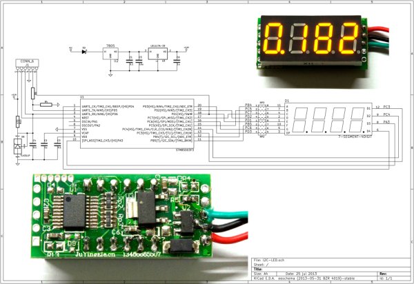
Along with the complexity grows exponentially from one solution to another, I slowly start to feel the importance of KISS concept, keep it simple stupid. All I need is just a number display, nothing fancy, nothing pricey, nothing takes my attention away from the analog circuitry. I decided to go back to the basic 7-segment LED display. “Simplicity is the ultimate sophistication”, how elegant it is!
I ordered several LED voltmeters from a taobao seller. It costs RMB16 each, about US$2.6 excluding shipping. The original design was for battery measurement on scooters. The advertised accuracy is 0.2%, which turns on my bullshit detector immediately. So the first thing I did after receiving it, was “don’t turn it on, tear it apart”. The manufacture did not scratch off the markings so the schematic can be easily traced out.
The heart of the voltmeter is “STM8S003F3P6″, a 8-bit MCU with 16MHz clock and 8K flash by STMicroelectronics. Datasheet shows this MCU has built-in 10-bit ADC. Driving 4 digits 10000 counts with 10-bit ADC is definitely overrating. While somebody may argue that ADC resolution can be increased using oversampling, without proper noise injection circuitry I cannot confirm it actually works. Furthermore the MCU does not have a dedicated ADC reference input. Supply voltage is used as reference. As the display needs to scan each digit continuously, supply fluctuation is inevitable. How to maintain ADC accuracy with changing reference? The original designer may have considered this problem initially. He/She added D9 (TL431 2.5V reference) and connected its output to analog input AIN6. So before measuring the input voltage at AIN5, 2.5V at AIN6 can be measured and then AIN5 calculated relatively. However D9 was not populated on the board I receive.
I was in the verge of desolder the LED and suddenly an idea bumped into me: why not reprogram this module and use it as a sole display? By doing so I can offload the LED driving task to the STM8. The original designer has reserved footprint for a 6-pin connector with SWIM programming/debugging interface and TX/RX serial port, reprogram should not be too difficult. A second thought is that it would be even better if I can emulate a popular serial LED module so that all existing codes can be used. The “Adafruit 4-digit 7-segment LED backpack” is soon identified. Ladyada did some remarkable work to develop Arduino library and wrote a tutorial for it. Make something compatible with her work is my honor.
For more detail: Hacking a cheap LED voltmeter
-
Why did the author choose a 7-segment LED display over OLED or TFT?
The author chose it to follow the KISS concept, avoiding complexity and ensuring the focus remains on analog circuitry. -
What is the cost of the LED voltmeter modules ordered?
They cost RMB16 each, which is about US$2.6 excluding shipping. -
What microcontroller is used as the heart of the voltmeter module?
The module uses an STM8S003F3P6 8-bit MCU with a 16MHz clock and 8K flash. -
Why is the advertised 0.2% accuracy considered suspicious?
A 10-bit ADC cannot properly drive 4 digits with 10000 counts without oversampling and noise injection, and the supply voltage acts as the reference causing fluctuations. -
How was the original designer's solution for ADC accuracy implemented?
The design included a TL431 2.5V reference connected to analog input AIN6 to calculate the input voltage at AIN5 relatively, though this component was not populated on the received board. -
What modification was made to use the module as a sole display?
The author reprogrammed the module to offload the LED driving task to the STM8 microcontroller. -
Which popular serial LED module does the modified code emulate?
The code emulates the Adafruit 4-digit 7-segment LED backpack to allow usage of existing Arduino libraries. -
What interfaces are available on the module for reprogramming?
The module has a reserved footprint for a 6-pin connector with a SWIM programming/debugging interface and a TX/RX serial port.
