Summary of Hand controller for Parrot AR Drone Quadricopter Using Atmega644
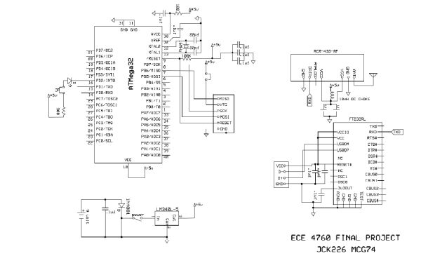
This project develops a handheld glove controller using an accelerometer to wirelessly operate a Parrot AR Drone. The system employs an ATMega32 microcontroller to read sensor data from the ADXL335 and a force sensor, transmitting commands via 433MHz radio modules. The design prioritizes low-cost components and DIP packaging for easy prototyping, utilizing a separate 9V battery and 3.3V regulator to ensure stable voltage for the accelerometer.
Parts used in the Handheld Glove Controller:
- ATMEGA32 Microcontroller
- Custom PC Board
- 9 Volt Battery
- RCT-433 Transmitter
- RCR-433 Receiver
- DIP Socket
- FTDI chip and USB connector
- Solder Board
- Gloves
- 3V Regulator
- Header Pins
- Force Sensor
- ADXL335 with breakout board
- 9V to Barrel Jack Converter
- 9V connector
Introduction
Our project is a novel hand held controller in which we use an accelerometer to wirelessly control the motion of a Parrot AR Drone Quadricopter.
Rationale:
The main idea of our project was building a cool glove controller for a flying platform, a quadrotor in this case, which would give the user a different sense of power over the robot, unlike conventional controllers like the Xbox controller. Even though this is an ambitious project that aims to make a moderately good controller, it can open the way to further development for this type of controllers for flying platforms. This is another reason for using a quadrotor from the Robot Learning lab. One of the team members(Mevlana Gemici) is merging this project with his project and research in the Robot Learning lab which is administrated by Prof. Ashutosh Saxena. This also allowed the quadrotor to be kept out of the budget considerations.

Background math: Other than very simple math, we didn’t need to do many calculations for our project. In fact, other than integration (very simple summing in time steps) in the receiver end, there is nothing worth mentioning.
Program/Hardware Design
We utilized the ATMega32 microcontroller in our program. Although we initially wrote our code for the ATMega644 microcontroller, we switched to using the ATMega32 chip, as it required only changes in registers names in the ATMega644 code.
We took care to select parts that were available in DIP packaging, so we could solder on to a prototype board.
Since we did not ask for any samples, we cut the budget fairly close. We already had several of the necessary items – the gloves and battery connectors/converters available so we did not count that in the budget.
Accelerometer
The accelerometer we chose was the ADXL335, which including a breakout board, we obtained for $20 from Adafruit. Our choice of this module was motivated by several factors. We needed a low-G accelerometer, since the acceleration that is being detected would not be too great, as our application would be controlled by a user moving his/her hand. Furthermore we wanted movement in the x, y, and z directions, and therefore we needed an accelerometer that can sense movement in all three of these axes. Furthermore, the accelerometer must be both low cost and available on a breakout board, as the cost of a PCB would definitely cause this project to run over-budget.
The accelerometer runs on voltage supplies of 1.8V to 3.6V. We opted to use 3.3V regulator along with a separate 9V battery to power the module. Initially we attempted to use a simple op-amp voltage shifter to shift the 5V from our microcontroller power supply to the 3.3V needed. However, the supply voltage provided by this setup proved to fluctuate quite a bit, causing the acceleration values from the accelerometer to fluctuate along with it, making it difficult for us to detect when it was actually accelerating. Therefore, we decided to swap to using the 3.3 V regulator and a separate power supply altogether, despite the increased weight of the extra 9V battery. This resulted in much more stable accelerometer readings.
We oriented the accelerometer such that the x axis was indicative of forward/backwards motion, the y axis indicates right/left motion, and the z axis indicates up/down motion. Therefore, at rest, there is 0g acceleration on the x and y directions, but there is a constant -1g on the z axis caused by gravity. At 0g acceleration, the voltage present on the outputs from each axis should be Vs/2, where Vs is the supply voltage provided to the accelerometer, which is 3.3 V in our case.
To acquire data from the accelerometer, we used the internal ADC in the microcontroller. The analog signals were connected in single ended channel configurations as follows – the z axis was connected to AD0, the y axis to AD1 and the x axis to AD2 of the microcontroller. As the ADC can only read one analog channel at a time, we used the internal multiplexer in the AVR to switch between these three ADC channels. The ADC value is read in the ADC interrupt service routine, which is called when the ADC has finished reading a value. We read all 10 ADC bits- that is from both the ADCL and the ADCH registers – but in retrospect, we only needed to read 8, as we ended up discarding the two least significant bits in order to compress the data to 2 bytes, as we can only send a limited amount of bytes in each data packet from the transmitter to the receiver. More on this will be elaborated in the section on wireless communication below.
Once the data was acquired at the receiver microcontroller, we output information acquired from it to the PC in a very specific format. Instead of sending the ADC values directly to the PC, we chose to send the change in the ADC values – that is, the change in the acceleration. While acceleration can be obtained by subtracting the rest position ADC value from the newly acquired ADC value, if we hard coded the ADC rest value in, it would confine the user to start at a very specific accelerometer orientation, and therefore would probably not be suitable for use on a glove one would be wearing. Therefore, we chose to send the change in acceleration. Doing so made determining direction of motion slightly harder than it would have if we simply passed in acceleration data because then it would have been possible to perform Euler integration to obtain a rough velocity value. The format in which we sent data into the PC is as in the picture below. X1 is the tens digit of the change in x acceleration and X0 is the ones digit. XDIR is 1 if the change is positive, and 0 if there is no change or it is negative. The same applies to Y1, Y0, YDIR, Z1, Z0, and ZDIR. Squeezed is 1 if the force sensor was toggled on and 0 if it is toggled off. Each data string starts with # and ends with * for easy identification in parsing.
The variable squeezed is 1 if the force sensor is pressed. We use the circuit in the below diagram to detect when the force sensor is pressed. When the force sensor is not pressed, its resistance is in the MOhm range. When it is pressed, its resistance approaches a short circuit. We therefore use the analog comparator to detect when the voltage rises above a certain value by setting it to detect on rising edge. This value can be set using a potentiometer and is useful for setting how sensitive a squeeze the sensor can register.
Even though we implemented the hardware as well as the software for this force sensor button, we couldn’t find a good use for it since take off and landing was controlled by another mechanism. However, we are planning to use this part in further development and research on this controller in the Robot Learning lab. One suggestion that we are considering is using this sensor to toggle on/off the control to allow longer motions without having to pull back the hand while the quadrotor is controlled. This would provide easier user control as was suggested by our TA, Rohan Sharma.
Wireless Communication
For the wireless communication between our transmitter unit and the receiver unit, we utilized the RCT-433-AS transmitter and the RCR-433-RP receiver, both from Radiotronix and provided by Professor Land. The communication protocol we used was heavily adapted from Meghan Desai’s Wireless Transmit and Receive Project Report on the course website. We made several modifications to it to better suit our project.
The original communication protocol on Meghan Desai’s page utilizes the following method to transmit data. The full documentation for his protocol is listed in the appendix below.
The transmitter sends data to the receiver through on-off keying, in which a logic 0 is transmitted by turning the transmitter off and a logic 1 is sent by turning the transmitter on, which sends out a carrier. In this configuration, the transmitter idles at logic 0. As the UART of the microcontroller idles at logic 1, the signal must first be passed into an inverter before being sent to the transmitter and the output from the receiver must then be inverted again. The inverter we used was a npn transistor placed in common emitter mode in the following configuration. Professor Land suggested using 1kOhm resistors for best performance.
he original protocol involved sending data from a transmitter to a receiver at a baud rate of 4000. However, as this is a non-standard baud rate, it was difficult to interface it properly with the PC, as we not used the USART ports of the microcontroller on the receiver end to accept data from the radio, we also used it to send data to the PC over a serial USB connection.
Parts List:
| Component | Vendor | Units | Cost Per Unit | Total Cost |
| ATMEGA32 | Bruce Land |
2 |
$1 |
$2 |
| Custom PC Board | Bruce Land |
2 |
$4 |
$8 |
| 9 Volt Battery |
3 |
$2 |
$6 |
|
| Transmitter RCT-433 | Bruce Land |
1 |
$4 |
$4 |
| Receiver RCR-433 | Bruce Land |
1 |
$4 |
$4 |
| DIP Socket | Bruce Land |
2 |
$0.50 |
$1 |
| FTDI chip and USB connector | Bruce Land |
1 |
$8.00 |
$8.00 |
| Solder Board | Bruce Land |
1 |
$2.50 |
$2.50 |
| Gloves |
1 |
FREE | FREE | |
| 3V Regulator | Sparkfun |
1 |
$1.95 |
$1.95 |
| Header Pins | Bruce Land |
40 |
$0.10 |
$4.00 |
| Force Sensor | AdaFruit Industries |
1 |
$7.00 |
$7.00 |
| ADXL335 with breakout board | AdaFruit Industries |
1 |
$20.00 |
$20.00 |
| 9V to Barrel Jack Converter |
2 |
FREE | FREE | |
| 9V connector |
1 |
FREE | FREE | |
| $68.45 TOTAL |
For more detail: CORNELL UNIVERSITY ECE 4760 FINAL PROJECT USING ATMEGA644
- How was the budget managed for this project?
The team cut the budget closely by using existing gloves and connectors, avoiding sample requests, and selecting low-cost parts like the $20 ADXL335 module. - Why did the team switch from ATMega644 to ATMega32?
The switch was made because the code required only changes in register names, making the transition simple while maintaining functionality. - What voltage supply was chosen for the ADXL335 accelerometer?
A 3.3V regulator powered by a separate 9V battery was selected to provide stable readings compared to fluctuating op-amp shifter setups. - How are the x, y, and z axes oriented on the accelerometer?
The x axis indicates forward/backwards motion, the y axis indicates right/left motion, and the z axis indicates up/down motion relative to gravity. - How is data compressed before wireless transmission?
Data is compressed to 2 bytes by discarding the two least significant bits of the 10-bit ADC value. - Does the system send absolute acceleration values or changes?
The system sends the change in acceleration rather than absolute values to avoid confining the user to a specific starting orientation. - How does the force sensor detect a squeeze?
The analog comparator detects when the voltage rises above a set threshold as the sensor resistance drops from MOhm range to near a short circuit. - What protocol is used for wireless communication?
The system uses on-off keying where logic 0 turns the transmitter off and logic 1 turns it on, adapted from a standard course project report. - Can the force sensor be used for takeoff and landing?
No, the force sensor could not find a good use for takeoff and landing as those were controlled by another mechanism. - What future use is planned for the force sensor?
Future plans include using the sensor to toggle control on and off to allow longer motions without pulling back the hand.