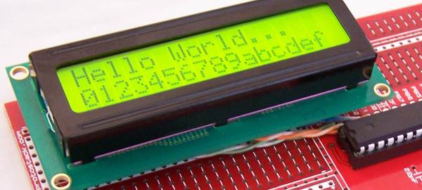
Summary of hd44780 Character LCD Displays – Part 2
This tutorial details connecting a 16-pin Character LCD module to an Atmega8 microcontroller using an AVR 28-pin development board. It covers circuit assembly, power supply connections via USB, and configuring the display in 4-bit mode to utilize only six I/O lines on Port C. The guide also explains adding a trimpot for contrast adjustment and wiring specific pins to ground or power rails.
Parts used in the Atmega8 Character LCD Project:
- AVR 28 pin Development Board
- USB to DC Barrel plug cable
- 16 pin female header
- 5K trimpot (potentiometer)
- Character LCD module
- Atmega8 microcontroller
Introduction
This tutorial continues from Character LCD Displays – Part 1. In this part we will connect the LCD module to an Atmega8 microcontroller, then write some code to drive it.
The Circuit
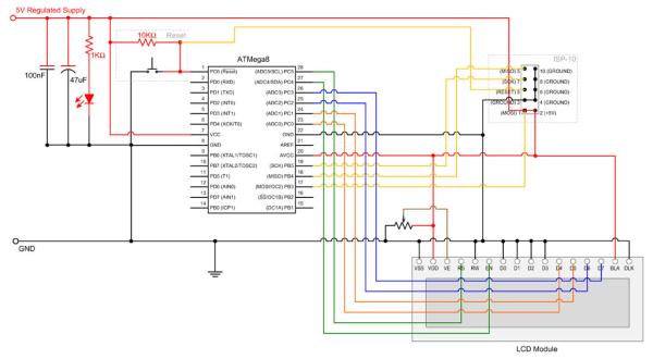
Our first task is to build the circuit.
We will be using an AVR 28 pin Development Board. For the power supply we will use a USB to DC Barrel plug cable, so we won’t need to build a 5V regulator circuit. Instead we will run a wire from the barrel connector to the positive power rail, as shown in the photo below.
Also we won’t need an external crystal or AVCC filter block. We still need to run power to AVCC and this is done with a piece of wire.
Because we want the ability to remove the LCD module later, we will solder a 16 pin female header to the board.
Next we wire-up VDD and BLA to the positive power rail along with VSS, RW, D0, D1, D2, D3 and BLK to the ground power rail. D0 to D3 are being tied to ground because we will drive the display in 4 bit mode. This lets us drive the display with just 6 I/O lines.
Next we add a trimpot for the LCD contrast. I used a 5K pot, but a range of other values would work as well.
We now connect RS, EN and D4-7 to PC0-PC5. These could have been connected to any of the atmega8 I/O ports, but port C seemed to be ideal as it has 6 usable I/O pins. If you decide to use other pins just change the source code accordingly.
Read More: hd44780 Character LCD Displays – Part 2
- How is the power supply provided in this project?
The project uses a USB to DC Barrel plug cable connected directly to the positive power rail. - Why are D0 to D3 tied to ground?
They are tied to ground because the display is driven in 4 bit mode. - What is the benefit of driving the display in 4 bit mode?
This configuration allows the display to be driven with just 6 I/O lines. - Which port is used for RS, EN, and D4-7 connections?
Port C (PC0-PC5) is used as it has 6 usable I/O pins. - Can other values be used for the trimpot?
Yes, a range of other values would work besides the 5K pot used. - Is an external crystal required for this setup?
No, an external crystal or AVCC filter block is not needed. - How can the LCD module be removed later?
A 16 pin female header is soldered to the board to allow removal. - Does the source code need changes if different pins are used?
Yes, the source code must be changed if you decide to use other pins.