Introduction:
Our project is a serial port-controlled, high resolution color television picture display.
We divided the project into the image transfer and storage portion and the television display portion. We opted for an RS-232 port for picture transmission because it involves a relatively simple, well-known protocol that will allow us to change the picture on a whim, rather than hard-coding an image into the microcontroller program.
In order to reach our goals in due time, we used an external chip to generate the synchronization timing, and another external chip to generate the color TV signal from a timed set of red, green, and blue voltages. Also, we greatly simplified our microcontroller code by having all of our active code inside a single external interrupt, triggered by the synchronization generator chip. With this method, we avoid duplicating the signal bookkeeping that the external chips also keep track of.
High Level Design:
The high-level design can be broken down into 3 major segments: serial port communication between the PC and microcontroller, image storage and retrieval from static RAM, and TV signal generation. The following diagram illustrates the major components and interactions of the system:
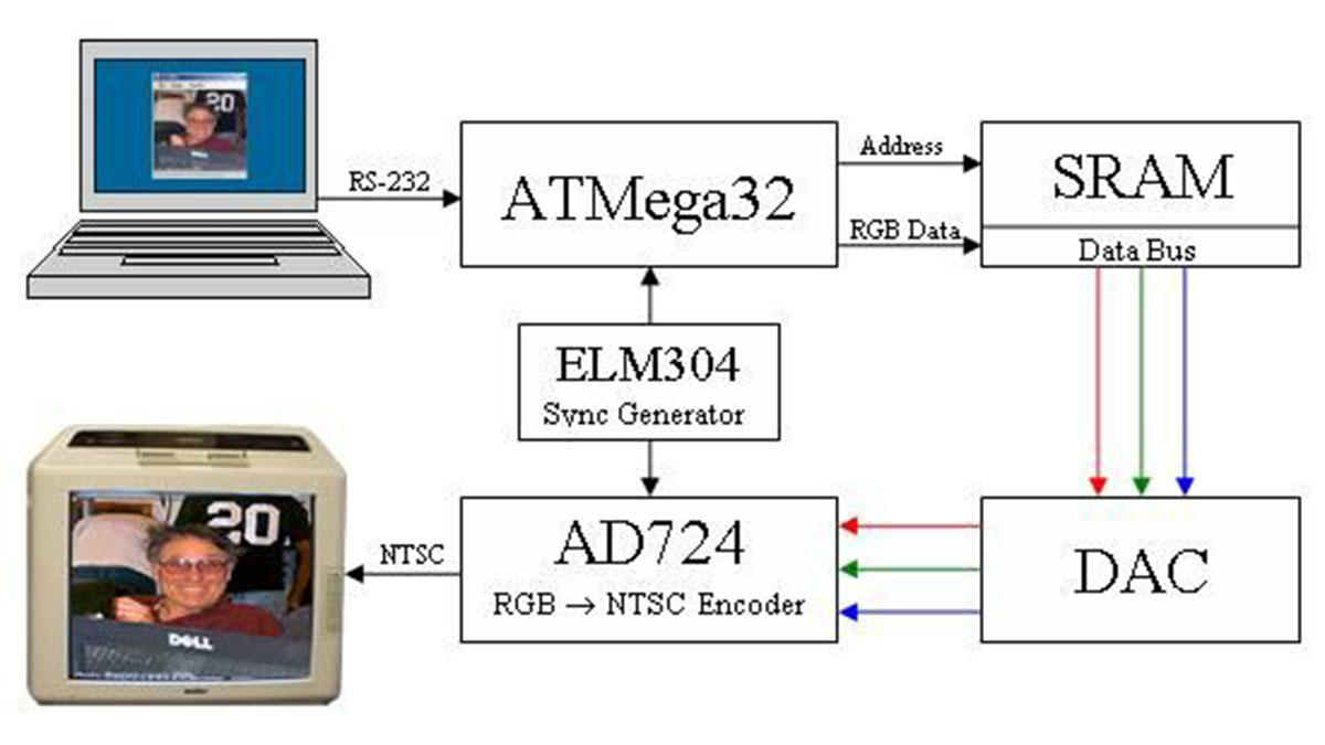
The microcontroller interfaces with a PC application via a RS-232 serial port to downloading an image into a static RAM chip on a whiteboard. To display pixels, the microcontroller simply deposits an address to the static RAM, which then provides the pixel to the DAC circuit. Each pixel is a single byte, allowing for 256 possible colors with 3 bits for red, 3 bits for green, and 2 bits for blue. The DAC takes these 8 bits of pixel data as input, separates out the individual colors’ bits, then uses three separate, smaller resistor networks to convert each color’s bits to an analog signal that is appropriate for the AD 724 chip which converts them into a single NTSC signal that is displayed on the television. The ELM304 provides a solid-white NTSC signal that is routed to both the microcontroller and the AD 724. The sync pulses from this signal trigger the line display interrupts on the microcontroller, and the blank signal is overlaid with color information by the AD 724.
Design Tradeoffs
Our design involved several tradeoffs between hardware and software complexity. Most notably, we opted to use software to discern horizontal and vertical syncs, rather than relying on an external sync separator. Though this required a delay in signal initiation for each line, this delay did not affect the visible portion of the television display. Furthermore, it was necessary to ensure that the color signals were turned off at the end of each line in order to preserve the integrity of the sync information. We opted for the simplest solution, which was to black out the rightmost two pixels of each line on the PC before sending it to the microcontroller, and as before this did not affect the visible portion of the display. This and other tradeoffs are discussed in greater detail in the low-level design sections that follow as well as in the conclusions.
Standard
Since this project exports a signal to a standard television, it must conform to the NTSC television standard. The NTSC standard has been used before, but only with black & white signals. For this project, we needed to include a 3.58 MHz sideband for the color TV signal, and also provide the red, green, and blue (RGB) values for this sideband. Our compliance with this standard is discussed in more detail in the hardware and software design sections.
The RS-232 serial port protocol was used for data loading from a PC. This protocol is based on the EIA232 standard, and compliance with this standard was handled by the System.IO.SerialPort class on the PC and the MAX233 chip on our board.
Hardware Design:
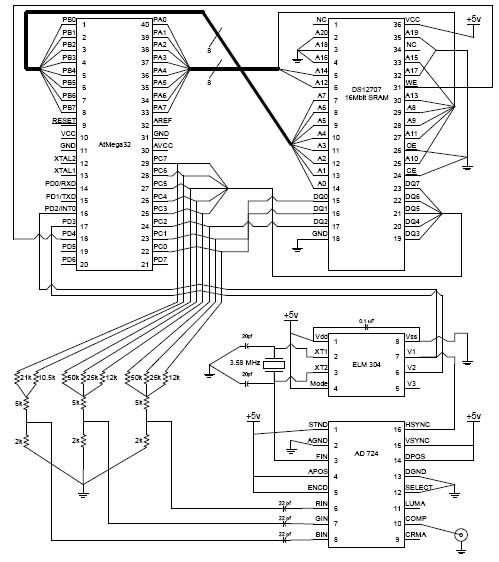
The circuit is largely the linking of the AtMega32 microcontroller with the ELM 304 NTSC Video Generator chip and the Analog Devices 724 RGB to NTSC encoder chip. These are also integrated with our static RAM image storage which is a Dallas Semiconductor DS1270 16 Mbit non-volatile RAM chip. (See appendix for a detailed schematic)
The most involved portion of circuitry was in building the resistor-network digital-to-analog converters. There are three of them: a 3-bit DAC for a “red” signal, a 3-bit DAC for a “green” signal, and a 2-bit DAC for a “blue” signal. As shown in the circuit schematic, each resistor network is a simple set of voltage adders, with input resistance adjusted to provide different “weights” for each bit of binary input, scaled by powers of two. For example, each input resistor has twice the resistance of the one preceding it. The output is then voltage-divided with another resistor from 5v down to 0.714v. This is because the AD724 chip expects the red, green, and blue inputs to be within the 0v -> 0.714v range.
The main problem we encountered with our original circuit was that the voltage regulator recommended for use with the protoboard (the LM340LAZ-5) was not capable of providing the necessary current to power the components of the system. The LM340LAZ-5 is only capable of supplying 100mA, and with the NVSRAM alone requiring 85mA, this was far from sufficient. As a result, the regulator would get extremely hot very quickly, and none of the components on the board would function properly. We therefore removed the LM340LAZ-5 and replaced it with its larger cousin, the LM340, which supplies up to 1A and completely fixed our problem.
ELM 304
The ELM 304 is central to our design, and it is important that we describe its behavior in some detail at this time. The ELM 304 has two main modes of operation, determined by the status of pin 4: pure white raster (pin 4 high) and grey color bar raster (pin 4 low).
This diagram from the NTSC’s online tutorial website demonstrates the timing constraints involved in each portion of a display line of the NTSC signal.
At the end of each low sync pulse (highlighted in green), the signal enters the back porch which lasts for 4.7s before either displaying a new (white) line if it was a horizontal sync or continuing through the rest of the vertical sync. The chips output pins V1-V2 have different values during each of these periods, and V3 is not relevant in this mode:
Signal Phase V2 V1 Sync L L Blanking L H 100% White H H
These values will be referenced later when discussing the software that interprets the signal.
Software Design:
The software portion of this system can be broken down into four sections: initialization, the display interrupt, PC-side image preparation, and the serial port image transfer system. The first three were implemented solely on the microcontroller, while the fourth required code on both the microcontroller and PC.
Initial Design Considerations
Because we were interfacing directly with 16 bits of static RAM addressing, 8 bits of static RAM data, and at least 5 bits for extra communications with chips and the serial port, we had to carefully designate Atmel pins for specific tasks. We allocated the eight port A pins for the high byte of static RAM addressing, the eight port B pins for the low byte of static RAM addressing, and the eight port C pins for bi-directional static RAM data communication. As for port D, pins 0 and 1 are reserved by the Atmel chip for serial port communication, and we needed pins 2 and 3 for external interrupt input from the ELM 304 chip. We used port D’s pin 4 for controlling the static RAM’s active-low write enable line.
We chose to develop the PC application in Microsoft Visual C# 2005 (acquired for free via Cornell ECEs MSDNAA license agreement), which runs on Microsofts .NET 2.0 framework and provides inherent functionality for loading and manipulating images as well as serial port communication. This allowed us to quickly and easily implement the functionality we desired.
Mega32 Initialization
Upon booting the microcontroller, the code initializes communication I/O ports A through D, and fills the static RAM with vertical color bars as a test image until an actual picture is downloaded (see results). Specific registers that are used for keeping television display state are also initialized, then external interrupt 0 is activated, and the main() function goes into an empty infinite loop.
Mega32 Display Interrupt
The entire screen display and serial code is contained inside of external interrupt 0. Because the external interrupt is the only active code that will be running, we end every interrupt by re-enabling interrupts and another empty infinite loop or a “sleep” command. With this method each interrupt is essentially going to interrupt itself, and we can skip the saving and restoring of microcontroller registers during the interrupt, trimming at least 8 cycles of delay per interrupt.
The external interrupt is triggered at the end of the ELM 304s sync pulse (when the V1 pin goes from low to high). The external interrupt code immediately starts counting out just over 75 cycles (at 16MHz, this is just over 4.7s), which is the timed delay of the “back porch” part of the signal, the time between the start of a display line and the actual displaying of pixels.
After this time has passed, the code checks the ELM’s “V2” signal, which will be high if the ELM is displaying “white” pixels. The atmega32 then starts outputting addresses to the static RAM, thereby feeding pixels to the DAC/tv-output circuit. Since this “wait-then-check” method takes approximately 5 cycles that should be spent outputting pixels, this in essence trades almost 2 pixels off the left side of the screen that aren’t normally visible anyways for a simpler display mechanism.
If, on the other hand, the interrupt handler code checks the ELM’s “V2” signal, and the result is a logic 0, then the Mega32 interprets this as a sign it should be in the vertical synchronization part of the TV display. The code that executes during vertical sync is the code that checks if there is an image transfer waiting on the serial port, and if so, services the request by stopping TV display and transferring the image to static RAM.
PC-Side Image Preparation
The PC application allows images of almost any file type (JPEG, GIF, TIF, BMP, PNG, among others) to be loaded via a Load File menu option, dragged from another application or folder, or pasted from another application via the Windows clipboard. The .NET platform provides the functionality to complete all of these tasks with one or two simple function calls. Once loaded, the image is copied into an off-screen buffer with a fixed 24 bits/pixel (1 byte each for red, green, and blue) format, which is repainted onto the screen during each repainting event. This image can be either stretched or cropped to fit the desired resolution.
Before transmitting the image, the color values of each pixel must be flattened from 24bpp into the 8bpp format our system uses for storage. This is accomplished by simply truncating each channel and concatenating the most significant 3, 3, and 2 bits from the red, green, and blue values, respectively. Finally, because a byte value of 0x01 represents a stop signal for the microcontroller, any pixel with this color value after flattening is changed to 0x00 (black). This particular choice of stop byte and replacement value were chosen to minimize the visual impact of the change, since almost black merely becomes pure black.
Parts List:
| Qty. | Item | Price |
| 1 | Atmel ATMega32 microcontroller | $8 |
| 1 | Analog Devices AD724 RGB -> NTSC Encoder | Free Sample |
| 1 | ELM 304 NTSC Video Generator | $6.89 |
| 1 | 3.58 MHz Oscillator | < $1.00 |
| 1 | Custom PC Board | $5 |
| 1 | Color TV | $10 Rental |
| 1 | Power Supply | $5 Rental |
| 1 | MAX233CPP RS232 Driver | Free Sample |
| 1 | RS232 Port | $2 |
| 1 | USB->Serial Adaptor | Free (in Lab) |
| 1 | Dallas Semiconductor DS1270 2MB NVSRAM | Free Sample |
| 1 | White Board | Free Scrounge |
| 1 | Solder Board | $2.50 |
| 1 | Resistors and Capacitors | Free (in Lab) |
| Total | $40.39 |
For more detail: High-Resolution Color Television Using Atmel Mega32