Summary of How to Install and Setup EAGLE
SparkFun’s tutorial explains installing and configuring EAGLE PCB design software, why to choose it, licensing limits, navigating the Control Panel, and installing SparkFun libraries. It covers opening example projects, keeping schematic and board editors synchronized, UI tweaks (background, grid), and beginning a schematic by creating a project, adding a frame, saving, and placing power-input parts for a Bare Bones Arduino schematic.
Parts used in the Bare Bones Arduino:
- 5.5mm Barrel Jack (PTH) — SparkFun-Connectors POWER_JACKPTH
- 0.1µF Ceramic Capacitor — SparkFun-Capacitors CAPPTH
- Voltage Supply Symbol — SparkFun-Aesthetics VCC
- Ground Symbol — SparkFun-Aesthetics GND
Introduction
Printed circuit boards (PCBs) are the backbone of every electronic gizmo out there. They’re not flashy like those microprocessors, or abundant like resistors, but they’re essential to making all components in a circuit connect together just right.
We LOVE designing PCBs here at SparkFun. It’s a love that we want to spread. It’s a skill that benefits electronics enthusiasts of every caliber. Through this and a series of tutorials, we’ll explain how to design a PCB using EAGLE: the same software we use to design all of our PCBs.
This first tutorial goes over how to install the software, and tailor-fit its interface and support files.
Why EAGLE?
EAGLE is one of many PCB CAD software’s out there. So you might ask: “What makes EAGLE so special?” We’re fond of EAGLE for a few reasons in particular:
- Cross-platform: EAGLE can run on anything: Windows, Mac, even Linux. This is a feature not too many other PCB design software’s can boast.
- Lightweight: EAGLE is about as svelte as PCB design software gets. It requires anywhere from 50-200MB of disk space (compared to the 10+GB more advanced tools might require). The installer is about 25MB. So you can go from download to install to making a PCB in minutes.
- Free/Low-Cost: The freeware version of EAGLE provides enough utility to design almost any PCB in the SparkFun catalog. An upgrade to the next license tier (if you want to make a profit off your design) costs at least two orders of magnitude less than most high-end tools.
- Community support: For those reasons, and others, EAGLE has become one of the go-to tools for PCB design in the hobbyist community. Whether you want to study the design of an Arduino board or import a popular sensor into your design, somebody has probably already made it in EAGLE and shared it.
Of course, EAGLE has its drawbacks too. More powerful PCB design tools out there might have a better autorouter, or nifty tools like simulators, programmers, and 3D viewers. For us though, EAGLE has everything we need to design simple-to-intermediate PCBs. It’s an excellent place to start if you’ve never designed a PCB before.
Download, Install, Run
EAGLE is available on Cadsoft’s (the developer company) download page. Grab the most recent version that matches your operating system (the software is available for Windows, Mac and Linux). It’s a relatively light download: about 45MB.
EAGLE installs just like any old program, it’ll self extract and then present you with a series of dialogs to configure the installation.
Licensing EAGLE
On the last screen of the installation process, you should be presented with a window like this:
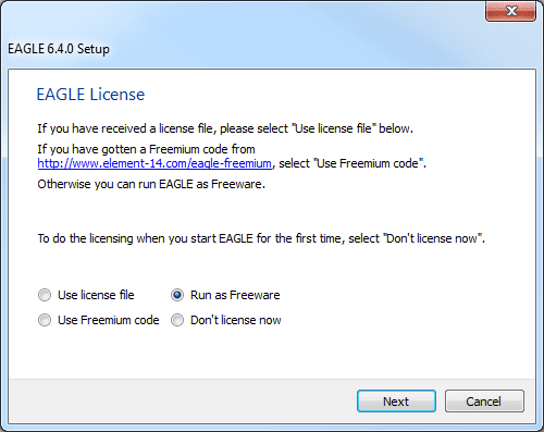
One of our favorite things about EAGLE is that it can be used for free! There are a few limitations to be aware of when using the free version:
- Your PCB design is limited to a maximum size of 100 x 80mm (3.94 x 3.15in). 12.4 in2 of PCB real estate, which is still pretty darn big. Even if you’re designing a big ‘ol Arduino shield, you’ll still be well under the maximum size.
- Only a two signal layers allowed. If you need more layers check into the Hobbyist or Standard licenses.
- Can’t make multiple sheets in your schematic editor.
- Limited to email or forum support.
- For non-profit use only. If you’re going to go out and sell your design, maybe check into the “Light” version of the software.
Those limitations still make EAGLE an amazing piece of software. Engineers here at SparkFun could design 99% of our boards using the freeware version, if not for that pesky non-profit stipulation. You still have access to all phases of the EAGLE software, including the Auto router.
If you need to upgrade your license there are a few versions available. Most licenses are still incredibly low priced (in comparing to the other stuff out there).
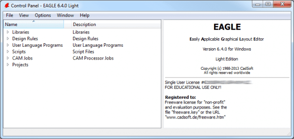
Exploring the Control Panel
The first time you open up EAGLE, you should be presented with the Control Panel view. The Control Panel is the “home base” for Eagle, it links together all of the other modules in the software.
You can explore the six separate trees in the control panel, which highlight separate functions of the software:
- Libraries: Libraries store parts, which are a combination of schematic symbol and PCB footprint. Libraries usually contain a group of related parts, e.g. the Atmel. lbr stores a good amount of Atmel AVR devices, while the 74xx-us.lbr library has just about every TTL 74xx series IC there is.
- Design Rules: Design rules are a set of rules your board design must meet before you can send it off to the fab house. In this tree you’ll find DRU files, which are a a pre-defined set of rules.
- User Language Programs (ULPs): ULPs are scripts written in EAGLE’s User Language. They can be used to automate processes like generating bill of materials (bom.ulp), or importing a graphic (import-bmp.ulp).
- Scripts: Script files can be used to customize the EAGLE user interface. In one click you can set the color scheme and assign key bindings.
- CAM Jobs: CAM jobs can be opened up by the CAM processor to aid in the creation of gerber files.
- Projects: This is where each of your projects are organized into a single project folder. Projects will include schematic, board design, and possibly gerber files.
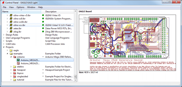
If you select a file in a tree, information about it will appear in the right-hand portion of the window. This is a great way to explore libraries, project designs (EAGLE comes with some fun examples), or to get a good overview of what a script’s purpose is.
Using the SparkFun Libraries
Included with EAGLE is an impressively list of part libraries, which you can explore in the Control Panel view. There are hundreds of libraries in here, some devoted to specific parts like resistors, or NPN transistors, others are devoted to specific manufacturers. This is an amazing resource! But it can also be a bit overwhelming. Even if you just want to add a simple through-hole electrolytic capacitor, there are dozens of libraries and parts to sort through to find the right thing.
Instead of using the hundreds of default libraries, you can use the SparkFun EAGLE Libraries, which are filtered down to only include the parts that we’ve used in designs ourselves. And they’re constantly updated with new parts we’ve discovered.
Here’s how you can install and use the SparkFun libraries instead of (or in addition to) the default ones:
Step 1: Download the SparkFun Libraries
The most recent version of the libraries can always be found in the GitHub repository. Basically, all you’ll need to do from the main repository page is click “Download ZIP”.
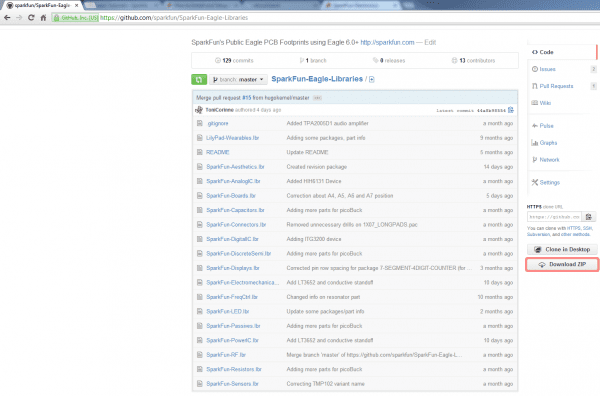
Save the ZIP file somewhere handy. Then extract the folder – don’t forget where it is!
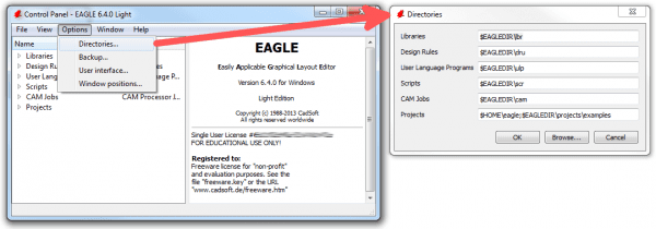
Step 2: Updating the Directories Window
Back to the EAGLE Control Panel window now. Go to the “Options” menu and then select “Directories”. This is a list of computer directories where EAGLE looks when it populates all six objects in the tree view…including libraries.
In the “Libraries” box is where we’ll add a link to the directory where the SparkFun EAGLE libraries are stored. There are a few options here. If you’d like to keep the default libraries and add the SparkFun library, add a semicolon (;) after “$EAGLEDIR\lbr”, and paste the SparkFun EAGLE Libraries directory location after that.
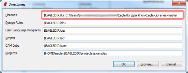
Note: Mac and Linux users should place a colon (:) between directories instead of the semicolon.
Step 3: “Using” Libraries
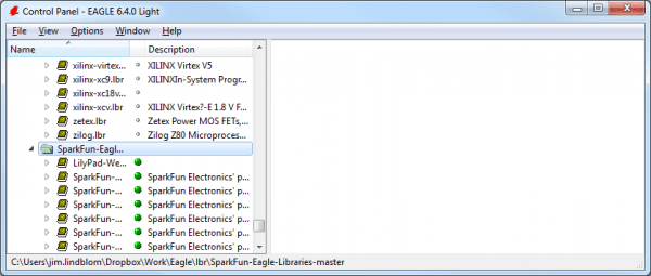
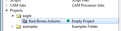
Now, when you go back and look at the “Libraries” tree, there should be two folders included, one of which should be our SparkFun Eagle Libraries. The last step is to tell EAGLE that, for now at least, we don’t want to use the default libraries. To do this, right click on the “lbr” folder, and select “Use none”.
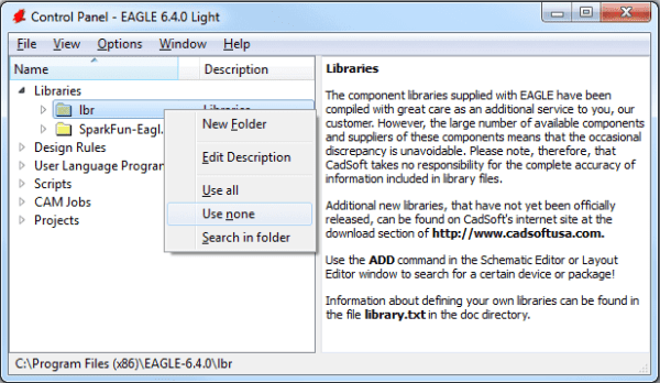
Then, right-click on the “SparkFun-Eagle-Libraries-master” folder, and select “Use all”. Then check the libraries in each of the two folders. Next to them should be either a grey or green dot. A green dot next to a library means it’s in use, a grey dot means it’s not. Your libraries tree should look a little something like this:
Opening a Project and Explore
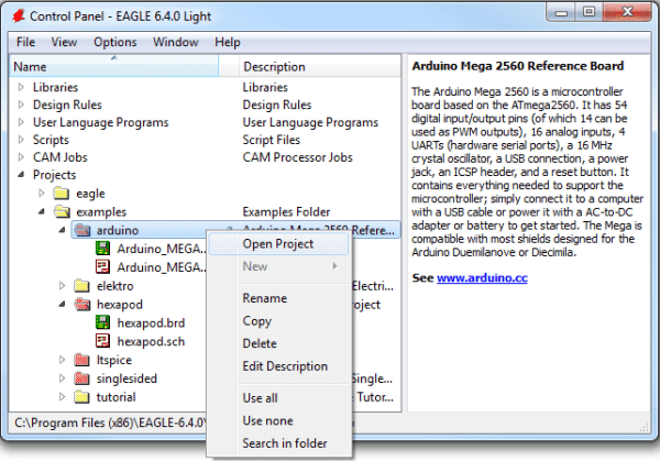
EAGLE is packaged with a handful of nifty example PCB designs. Open one up by expanding the “Projects” tree. From there, under the “examples” folder open up the “Arduino” project by double-clicking the red folder (or right-clicking and selecting “Open project”). Note that, in this view, project folders are red and regular folders are the standard yellow.
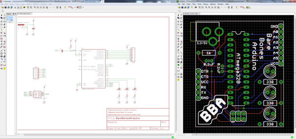
Opening the project should cause two more EAGLE windows to spawn: the board and schematic editors. These are the yin and the yang of EAGLE. They should be used together to create the finished product that is a functional PCB design.
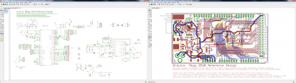
Schematic (left) and board editors both open. Click to embiggen.
The schematic editor (on the left above) is a collection of red circuit symbols which are interconnected with green nets (or wires). A project’s schematic is like the comments in a program’s code. It helps tell the story of what the board design actually does, but it doesn’t have much influence on the end product. Parts in a schematic aren’t precisely measured, they’re laid out and connected in a way that’s easy to read, to help you and others understand what’s going on with the board design.
The board editor is where the real magic happens. Here colorful layers overlap and intersect to create a precisely measured PCB design. Two copper layers: red on top, blue on the bottom: are strategically routed to make sure different signals don’t intersect and short out. Yellow circles (on this design, but they’re more often green) called “vias” pass a signal from one side to the other. Bigger vias allow for through-hole parts to be inserted and soldered to the board. Other, currently hidden, layers expose copper so components can be soldered to it.
Keep Both Windows Open!
Both of these windows work hand-in-hand. Any changes made to the schematic are automatically reflected in the board editor. Whenever you’re modifying a design it’s important to keep both windows open at all times.
If, for instance, you closed the board window of a design, but continued to modify a schematic. The changes you made to the schematic wouldn’t be reflected in the board design. This is bad. The schematic and board design should always be consistent. It’s really painful to backtrack any changes in an effort to reattain consistency. Always keep both windows open!
There are a few ways to tell if you don’t have consistency between windows. First, there’s a “dot” in the lower-right hand corner of both windows. If the dot is green, everything is groovy. If the dot is magenta, a window’s probably closed that shouldn’t be. Second, and more obvious, if you close either of the two windows a big, huge warning should pop up in the other:
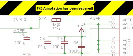
If you see that warning STOP doing anything, and get the other window back open. The easy way to get either a board or schematic window back open is by clicking the “Switch to board/schematic” (also found under the “File” menu).
This is a subject that’s usually glazed over, but it’s important to know how to navigate around both of these windows.
To move around within an editor window, a mouse with a scroll wheel comes in very handy. You can zoom in and out by rotating the wheel forward and backward. Pressing the wheel down, and moving the mouse allows you to drag the screen around.
If you’re stuck without a three-button mouse, you’ll have to resort to the view options to move around the editor views. All of these tools are located near the middle of the top toolbar, or under the “View” menu. The zoom in: : and zoom out: : tools are obviously handy. So is the “Zoom select” tool: : which alters the view to your selection. But really, if you’re serious about using EAGLE…get a mouse!
Configuring the UI
EAGLE’s user interface is highly customizable. Anything from the background color, to layer colors, to key bindings can be modified to fit your preference. Better tailoring your interface can make designing a PCB much easier. On this page we’ll talk about how we at SparkFun prefer to customize our UI. None of these steps are required. Customize your UI as you see fit. These are just the settings that we’ve grown accustomed to.
Setting the Background Color
The first adjustment we always make to the UI is the background color of the board editor. The standard white background doesn’t always meld very well with the array of colored layers required for board design. Instead, we usually opt for a black background.
To change the background color, go up to the “Options” menu and select “User interface”.
Inside the “Layout” box you can set the background to black, white, or a specific color.
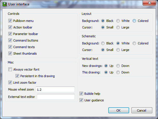
There are other options in this box to be explored, but you may want to hold off on adjusting most until you have more experience with the software.
Adjusting the Grid
Another UI improvement we like to make in the board editor is turning the grid on. Dimensions and sizes are so important to the design of your PCB, having some visible reminders of size can be very helpful. To turn the grid view on, click the icon near the top-left corner of the board window (or go to the “View” menu and select “Grid”).
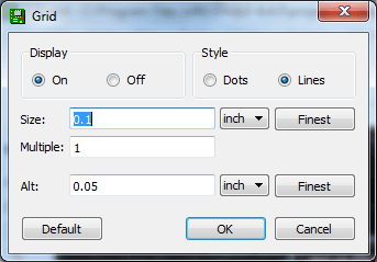
Switch the “Display” radio button over to “On”. We’ll also make the grid a bit less fine by setting the “Size” to 100 mil (0.1″) and “Alt” to 50 mil (0.05″).
Using EAGLE: Schematic
Introduction
PCB design in EAGLE is a two-step process. First you design your schematic, then you lay out a PCB based on that schematic. EAGLE’s board and schematic editors work hand-in-hand. A well-designed schematic is critical to the overall PCB design process. It will help you catch errors before the board is fabricated, and it’ll help you debug a board when something doesn’t work.
This tutorial is the first of a two-part Using EAGLE series, and it’s devoted entirely to the schematic-designing side of EAGLE. In part 2, Using EAGLE: Board Layout, we’ll use the schematic designed in this tutorial as the basis for our example board layout.
Create a Project
We’ll start by making a new project folder for our design. In the control panel, under the “Projects” tree, right click on the directory where you want the project to live (by default EAGLE creates an “eagle” directory in your home folder), and select “New Project”.
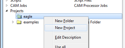
Give the newly created, red project folder a descriptive name. How about “Bare Bones Arduino”.
Project folders are like any regular file system folder, except they contain a file named “eagle.epf”. The EPF file links your schematic and board design together, and also stores any settings you may have set especially for the project.
Create a Schematic
The project folder will house both our schematic and board design files (and eventually our gerber files too). To begin the design process, we need to lay out a schematic.
To add a schematic to a project folder, right-click the folder, hover over “New” and select “Schematic”.
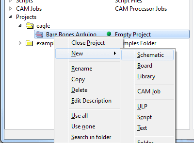
A new, blank window should immediately pop up. Welcome to the schematic editor!
Adding Parts to a Schematic
Schematic design is a two step process. First you have to add all of the parts the schematic sheet, then those parts need to be wired together. You can intermix the steps: add a few parts, wire a few parts, then add some more: but since we already have a reference design we’ll just add everything in one swoop.
Using the ADD Tool
The ADD tool: (on the left toolbar, or under the Edit menu): is what you’ll use to place every single component on the schematic. The ADD tool opens up a library navigator, where you can expand specific libraries and look at the parts it holds. With a part selected on the left side, the view on the right half should update to show both the schematic symbol of the part and its package.
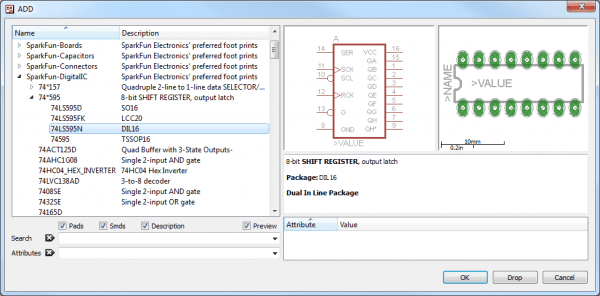
The ADD tool also has search functionality: very helpful when you have to navigate through dozens of libraries to find a part. The search is very literal, so don’t misspell stuff! You can add wildcards to your search by placing an asterisk (*) before and/or after your search term. For example if you search for atmega328 you should find a single part/package combo in the SparkFun-DigitalIC library, but if you search *atmega328* (note asterisks before and after), you’ll discover two more versions of the IC (because they’re actually named “ATMEGA328P”). You’ll probably want to get accustomed to always adding an asterisk before and after your search term.
To actually add a part from a library either select the part you want and click “OK”, or double-click your part.
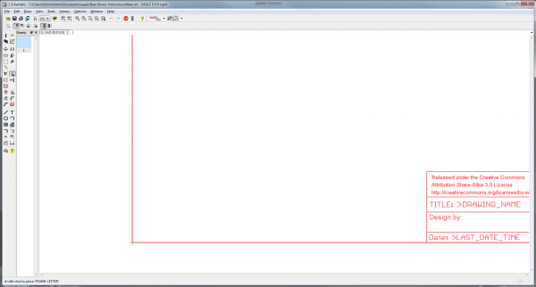
Step 1: Add a Frame
The frame isn’t a critical component for what will be the final PCB layout, but it keeps your schematic looking clean and organized. The frame we want should be in the SparkFun-Aesthetics library, and it’s named FRAME-LETTER. Find that by either searching or navigating and add it to your schematic.
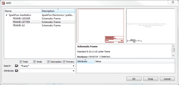
After selecting the part you want to add, it’ll “glow” and start hovering around following your mouse cursor. To place the part, left-click (once!). Let’s place the frame so its bottom-left corner runs right over our origin (the small dotted cross, in a static spot on the schematic).
After placing a part, the add tool will assume you want to add another: a new frame should start following your cursor. To get out of the add-mode either hit escape (ESC) twice or just select a different tool.
Step 2: Save (And Save Often)
Right now your schematic is an untitled temporary file living in your computer’s ether. To save either go to File > Save, or just click the blue floppy disk icon: . Name your schematic something descriptive. How about “BareBonesArduino.sch” (SCH is the file format for all EAGLE schematics).
As a bonus, after saving, your frame’s title should update accordingly (you may have to move around the screen, or go to View > Redraw).
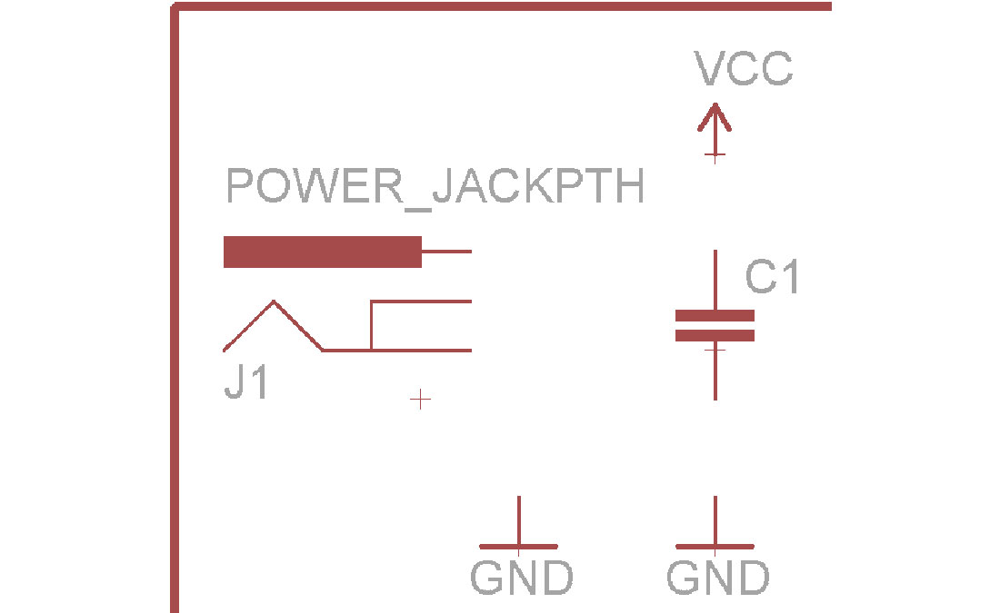
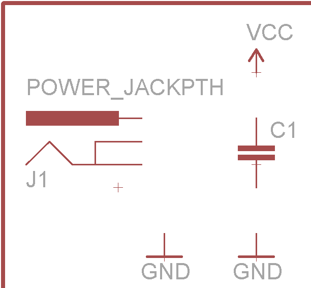
Step 3: Adding the Power Input
Next we’ll add four different parts all devoted to our voltage supply input. Use the add tool for these parts:
| Part Description | Library | Part Name | Quantity |
|---|---|---|---|
| 5.5mm Barrel Jack (PTH) | SparkFun-Connectors | POWER_JACKPTH | 1 |
| 0.1µF Ceramic Capacitor | SparkFun-Capacitors | CAPPTH | 1 |
| Voltage Supply Symbol | SparkFun-Aesthetics | VCC | 1 |
| Ground Symbol | SparkFun-Aesthetics | GND | 2 |
All of these parts will go in the top-left of the schematic frame. Arranged like this:
Source: How to Install and Setup EAGLE
- How do I get EAGLE for my operating system?
Download the most recent version matching your OS from Cadsoft's download page (Windows, Mac, Linux). - Can I use EAGLE for free?
Yes; the freeware version is available with limitations like max board size 100 x 80 mm, two signal layers, no multiple schematic sheets, limited support, and non-profit use only. - What are the Control Panel trees used for?
They organize Libraries, Design Rules, ULPs, Scripts, CAM Jobs, and Projects for easy access and management. - How do I add the SparkFun EAGLE libraries?
Download the SparkFun Libraries ZIP from GitHub, extract it, then add its directory under Options > Directories > Libraries in the EAGLE Control Panel. - How do I make EAGLE use only the SparkFun libraries?
Right-click the default lbr folder and select Use none, then right-click the SparkFun-Eagle-Libraries-master folder and select Use all. - How should I keep schematic and board editors while editing?
Keep both windows open at all times so changes in the schematic are reflected in the board; check the lower-right dot (green is good, magenta indicates an issue). - What UI changes does SparkFun recommend?
They suggest switching the board editor background to black and turning the grid on with size 100 mil and Alt 50 mil. - How do I start a new project and schematic?
Create New Project under the Projects tree, name it, then right-click the project folder, choose New > Schematic to open the schematic editor. - How do I add parts to a schematic?
Use the ADD tool to browse libraries or search (use wildcards like *term*), select a part, and place it by left-clicking. - What power-input parts are added for the Bare Bones Arduino schematic?
The tutorial adds a 5.5mm Barrel Jack (POWER_JACKPTH), a 0.1µF Ceramic Capacitor (CAPPTH), a Voltage Supply Symbol (VCC), and Ground Symbols (GND).