
Summary of How to Use ADC (Analog to Digital Converter) in AVR – Atmega32
This article explains how to use the Atmega32 microcontroller's built-in ADC to read analog signals from an LM35 temperature sensor, enabling a fire alarm system that triggers at 60°C. It details configuring the reference voltage via the ADMUX register and outlines essential hardware connections for stability, such as linking VCC to AVCC and adding capacitors to filter noise.
Parts used in the Fire Alarm Project:
- LM35 Temperature Sensor
- Atmega32 Microcontroller
- Buzzer
- Coil (Inductor)
- Capacitor
- VCC Power Supply
- GND Ground Connection
Using LM35 Sensor and Atmega32 ADC to measure Temperature
Analog to digital conversion is generally needed whenever we deal with a sensor that produces an analog output (for example: LM35 temperature sensor), which is the case for a wide range of sensors. When dealing with such sensors we have to convert the analog signal coming out of them into digital words of ones and zeros so that our microcontroller can process it and make decisions based on it. In order to do that we need a device called an ADC (Analog to Digital Converter) and fortunately, many controllers now have this device built-in.
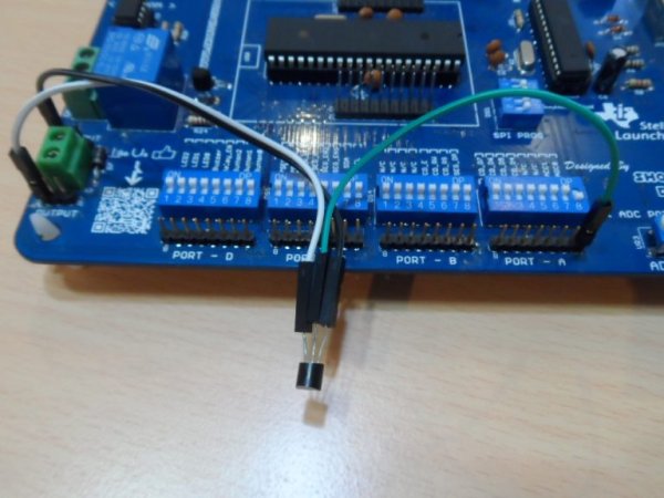
In this article, we shall learn about using the ADC of the Atmega32 to convert an analog signal to a digital one. As an example of an analog signal, we shall use the output signal coming out of the LM35 temperature sensor. By the end of this article, we will be able to make a simple fire alarm that triggers a buzzer when the temperature exceeds a certain limit (60 Celsius degrees as an example).
ADC Reference Voltage
The reference voltage is the maximum voltage you are expecting to receive from the sensor on the input channel of the ADC. In Atmega32 you can use one of three sources for the reference voltage:
- An internal voltage from within the Atmega32 MCU. This voltage is set to 2.56V and cannot be changed.
- The AVCC pin can be your reference voltage, but this pin must be connected to the VCC and in this case, your reference voltage is the VCC
- Finally, you can use your own customized reference voltage by connecting a voltage source that has the same value as the reference voltage you want to the pin AREF (pin32).
Choosing between these three sources of reference voltage happens while configuring the ADMUX register as we will explain later in this article. We will use the internal voltage option.
Hardware Requirements:
Before using the ADC of the Atmeg32 there are a few hardware connections required in the circuit so that you can get the best results:
- You should make sure that pins (VCC & AVCC) that are pins (10 & 30) are connected. This is because the ADC gets its power supply from the AVCC pin.
- If conversion accuracy is critical all the time, it is preferable that you connect a coil between the 2 pins and a capacitor between AVCC and GND. These 2 connections make the supply voltage of the ADC more stable and not easily fluctuated by noise.
- Also, it is preferable to connect a capacitor between AREF and GND so that the reference voltage of the ADC is more stable and not affected by noise. (Even if you choose to use the internal voltage or the AVCC)
- If you are going to use an external reference voltage, then you should connect it to the AREF pin. In this article, we will use the internal reference voltage so we will not need this step.
Atmega32 ADC Input Channels
ADC of the Atmega32 can accept inputs from up to eight channels. This means that you can connect up to eight analog input signals to the Atmega32 ADC, but at each conversion, only one channel input is converted. So, at each conversion, you should first choose the input channel to convert before starting the conversion. This is also done in the ADMUX register.
Read more: How to Use ADC (Analog to Digital Converter) in AVR – Atmega32
- What is the purpose of the ADC in this project?
The ADC converts analog signals from sensors like the LM35 into digital words so the microcontroller can process them. - How many input channels does the Atmega32 ADC support?
The Atmega32 ADC can accept inputs from up to eight channels simultaneously. - Which reference voltage option is selected in this article?
The internal voltage option set to 2.56V within the Atmega32 MCU is used. - Why should pins VCC and AVCC be connected?
Pins 10 and 30 must be connected because the ADC gets its power supply from the AVCC pin. - How can you make the ADC supply voltage more stable?
Connecting a coil between the two power pins and a capacitor between AVCC and GND stabilizes the supply voltage. - Does the AREF capacitor connection matter if using internal voltage?
Yes, it is preferable to connect a capacitor between AREF and GND even when using internal voltage to prevent noise. - Can you use an external reference voltage with the Atmega32?
Yes, you can connect a customized voltage source to the AREF pin (pin 32) to use an external reference. - What happens before starting a conversion on the ADC?
You must first choose the specific input channel to convert before starting the conversion process.
