Introduction
A modern-day twist on the classic theremin musical instrument.
This project uses two IR sensors and the ATMEGA1284P microcontroller to create an inexepensive, easy-to-use theremin. The theremin is a musical instrument which is controlled by the electromagnetic field your body body produces naturally. One hand is used to control the volume of the instrument, and the other hand controls the pitch.

We recreated this old-school instrument with a modern twist using two IR sensors to compute the location of each of the user’s hands. Each sensor outputs a voltage inversely proportional to its distance from the user’s hand. The microcontroller converts this analog signal to an 8-bit binary number upon which it can process the information and actuate the output of the theremin. Thus, with two sensors, an inexpensive microcontroller, and a few analog components for filtering, we have created a compact, inexpensive, and user-friendly version of the antiquated theremin.
High-Level Design
The theremin has been in existance for almost 100 years. It’s wavering sound can be heard on the Beach Boys’ track Good Vibrations , and perhaps more famously, in Led Zeppelin’s live performances of Whole ‘Lotta Love. While the physics that the theremin exploits in creating its sound are subtle and complicated, the sounds it produces are typically quite simple. Thus, it was clear that these sounds could be replicated with a simple 8-bit pulse-width-modulator through direct digital synthesis.
First, look-up tables for our desired periodic output signals are computed. These look-up tables each consist of 256 8-bit signed numbers. For the simple sine wave signal, this table represents 256 samples of a single period of sine wave, scaled to fit within the bounds of a signed character. As the theremin operates, a wrapping accumulator keeps track of the index into this lookup table. For increased precision, we use a 32-bit accumulator and index into the lookup table using the eight most-significant bits of this accumulator. When higher or lower frequency outputs are desired, the increment amount per time step is increased or decreased, respectively.
To determine the amount by which to increment the accumulator, we simply multiply the maximum accumulator amount (2^32) by the ratio of the desired output frequency and the inverse time slice–or frequency of output updating. This makes sense, as if the desired frequency is equal to the update frequency, the accumulator will overflow and wrap on each time slice. If the desired frequency is one tenth of the update frequency, the accumulator will overflow every ten time slices.
The IR sensor for pitch is A/D converted and mapped from the minimum desired frequency to the maximum desired frequency. On every time slice, this mapped frequency is multiplied by the constant terms described above to determine the accumulator increment value. The eight most-significant bits of the accumulator are then used to index into the signal lookup table, yeilding an 8-bit number. Meanwhile, the IR sensor for volume is A/D converted and mapped to a multiplicative constant by which the 8-bit number is scaled before being actuated.
To actuate the sound, the resulting 8-bit number is sent to a pulse-width-modulator on the microcontroller. This circuit produces a square wave with duty cycle proportional to the number provided to it. By low-pass filtering this signal, an analog approximation of our intended periodic signal is made.
To toggle between different output sounds, a simple pushbutton is provided to the user. This circulrly cycles through the available sounds and updates the lookup table into which the accumulator looks when computing the output value.
In order to create smooth volume and pitch changes, and to remove unpleasant jumps due to extraneous sensor readings, the ouputs of the sensors must be filtered before they can be used for computation. Because the microcontroller is under heavy load from the direct-digial synthesis, we chose to perform this through prefiltering in circuitry. Each sensor output is low-pass filtered before it is read by the microcontroller. It is worthwhile to note that causal low-pass filtering introduces a latency at the output. However, by using small enough capacitance in these filters, these latencies are made insignificant and un-noticable.
Program/Hardware Design
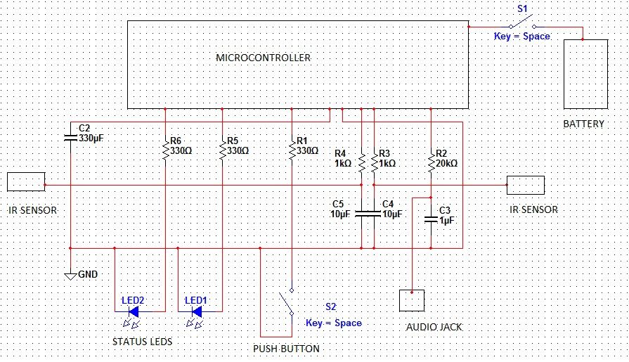
The hardware for this project consisted of the microcontroller, two infrared distance sensors, a power switch, push button, on/off LEDs, output audio jack, and various resistors and capacitors for inputs as well as various filters in the circuit.
The most important piece of hardware is the infrared distance sensor. The sensors used in this project have a ground, VCC, and signal pin. With ground and VCC connected to the ground line and 5V line respectively, the signal is wire is connected to the microcontroller port for analog to digital conversion through a low pass filter. The low pass filter used for the sensors is a passive filter with a cutoff frequency of 16 Hz to remove noise.
The output waveform is produced by pulse width modulation (PWM) and the PWM output pin is connected to the output audio jack. Two additional I/O ports are used to control 2 LEDS. A red LED is turned on when the device is initially powered but in its initialization phase. This red LED is turned off and a green LED turned on when the device has finished initialization and is ready to be played. All LEDs are wired to the port pins through 330 ohm resistors to limit the current on the port pins. To cycle through available instruments, a third I/O port is wired to push button through a 330 ohm resistor.
Finally, the power switch connects a 9V battery to the microcontrollers power supply. A 330 microfared capacitor is wire across the VCC and ground lines to filter out any noise on the power line when the sensors pull large bursts of current.
The majority of the software functionality lies inside of interrupt handlers in the code. In fact, the main method of our software only calls various initialization functions before going into an infinite loop whereby the rest of the operation of the theremin is controlled by interrupt handlers. This ensures consistancy with respect to timing, as each of our required tasks runs at a predictable rate. With this in place, we can be sure that all deadlines are met and that the software runs as expected all of the time. Four initialization functions are used to initialize the analog to digital converter (ADC), the pulse width modulation (PWM), timer 1, and timer 2.
The ADC is initialized to convert analog signals based on the reference voltage 3.5V which is the maximum output voltage of the sensors. Timer 1 is initialized to keep a 125 millisecond period on which the compare-match interrupt is triggered. Inside this interrupt vector, a single analog to digital conversion is read for either channel 0 or channel 1 and the channel is then toggled to convert the other channel on the next interrupt. This updates internal variables for pitch and volume based on the ADC values from the infrared distance sensors.
The PWM is set up on timer 0 of the microcontroller which runs at full speed. When the timer 0 overflow interrupt is triggered, a new value for the PWM is set. An accumulator variable is incremented by an amount proportional to the pitch reading from the infrared sensor. This accumulator is used to index into an array which holds a sampled period of the analog waveform that we want to produce. Different arrays are used to hold sampled periods of different instruments. Finally, the signal is then multiplied by a value proportional to the volume reading from the infrared sensor. This incorporates the pitch and volume readings into the generated signal. The pitch and volume readings generated by the ADCs are unsigned 8 bit numbers. We use these readings to index into a pitch and volume array which maps the sensor reading to the value we want for pitch and volume respectively. This is used to adjust the response characteristics of the theremin. For our theremin we used a mapping that creates a linear change between pitch and distance to sensor as well as between volume and distance to sensor.
In addition, timer 2 is initialized to control a de-bouncing finite state machine for the push button, running at 30Hz.
After this initialization is complete all of the functionality of software resides in the timer interrupt vectors.
One of the challenging parts of the project was generating different interesting sounds. In the initialization phase of the program, different tables are generated as sample periods of the sounds we want to generate. In addition to offering a simple sine wave for comparison, we combine different waves and modulation effects to generate different sounds.
Results
The final product we have created is an excellent substitution for a real theremin. It is very responsive to the user’s gestures, and these responses are consistent and re-createable. It is held in a secure enclosure which mimics the look of a classic theremin.
The theremin requires approximately three seconds to initialize before sound can be produced. This latency is made explicit to the user through a status LED which is red during initialization and green when it is ready to produce sound. Once initialization has completed, the user may control the volume and pitch of the output using his or her hands, and may switch the toggle through four instrument voices using the pushbutton on the front of the enclosure. A plot of five periods of each of our voices is shown in the following diagrams:
The input from the pitch sensor is mapped using a square-root mapping. This allows for greater precision in the low frequencies and greater ease of play.
s the plot shows, a full octave from middle C to C5 can be played over a comfortable range of approximately 30cm or one foot. Over this range, the distance-frequency relationship becomes close to linear, such that a person with only a little musical experience can quickly calibrate themselves to the responses of the instrument. The input from the volume sensor, too is mapped using a square-root mapping. However, to allow for muting when the users hand is not present or is very far away, a dead-region is intoduced. In this region, the amplitude of the output is always zero. This dead zone is set such that it is outside of the one-octave range described above so as to not interfere with normal plying.
t is worthwhile to note that this amplitude response is inconsistant with the response of a real theremin. For the classic theremin, full volume occurs at infinity, and muting occurs at zero distance. We chose to invert this mapping so that the default state would be silent. Thus, inless the user deliberately puts his or her hand in the proximity of the volume sensor, no sound will be produced. We feel this was appropriate for the academic setting in which this product was developed where constant sound would be undesirable. Should we find this inconsistancy to be undesirable, it can be very quickly changed to mimic that of a classic theremin.
Future Changes
In designing this product, we formulated a number of additions that we wish to pursue in the future. The first addition would be make the theremin more customizable. We could provide switches to select different modes–including one to switch between the current volume mapping and the classic theremin mapping. When designing the analog filters for the sensors, we found that filters with large capacitances introduced cool latency effects with respect to users’ movements. These filters could be selected and integrated into the design as well.
A greater, more long-term goal that we wish to pursue is to make this product an educational tool. By introducing a self-teaching mode, this device can be used to teach users how to play the theremin, and about music in general. An array of LED’s could show the user the appropriate locations to place there hands so as to play the different notes in a desired scale, and informaiton abour real songs can be encoded in the theremin to change these LED arrays to teach the user to play a number of different songs.
Conclusions
Overall, we were very pleased with the device we created. Our theremin reliably produces a clean sound and is very responsive to the user’s movement both in terms of volume and pitch. We had hoped to implement realistic-sounding instruments for the theremin to produce. However, due to tight timing constraints with the microcontroller, concessions had to be made in producing our sounds. Future iterations of the design could bypass the pulse-width-modulation by using an external digital to analog converter for output actuation. This would free up CPU time to leave additional cycles and memory for more complicated sounds. Also, in its current state, our theremin requires an external amplifier and speaker connected through a standard 3.5mm audio jack. In order to make our theremin truley portable, a built-in amplifier and speaker would be necessary. Furthermore, our input from the user comes in the form of a single-axis distance sensor. Movements which the user makes which are orthogonal to this axis are not seen by our theremin, and produce no response. This is the biggest discrepancy between our theremin and the real theremin, which responds to all user movements of all magnitudes.
All of the code run on the microcontroller was written by ourselves, although some of it–namely the pulse-width-modulation code–was recycled from previous 4760 lab assignments we wrote. To our best knowledge, there are no competing products or patents to our product, and we did not need to undergo any legal processes in legally producing it. While our product–upon further refinement–may have a market as a toy, instrument, or novelty item, it is unlikely that this device is patentable or publishable.
We feel as though we strictly followed the IEEE code of ethics in completing this project. As stated before, all of the code written for this project is original and written by ourselves. This code, while overall very simple, is completely composed or algorithms we conceived, or are boilerplate mechanisms (i.e. button debounce state machines). We by no means intend to exploit this product for monetary gains it is instead an exercise in efficient use of a microcontroller and a demonstration to the public of the immense flexibility and power of these devices when operated properly.
In sharing our product with the public, we are honest in its capabilities as well as its shortcomings. It is by no means an improvement on the original theremin in terms of quality of sound or responsiveness, nor do we intend to market it as such. Instead, we present this product for educational and enjoyment purposes.
We do, however maintain that this product is completely safe and without bias to persons of any gender, race, sexual orientation, or capability. The product is safe to use by any person of any familiarity with the theremin, or electronics or music as a whole. Because of its educational nature, we are welcome and open to criticism and suggestion on how this product can be improved in terms of efficiency, reliability, performance, or safety.
Appendix
Re-Creation Costs
This project can be recreated for $37.40. A detailed cost breakdown with specific parts listings can be found here.
Source Code
To run our software on the ATMEGA 1284P, you will need Theremin.c and Theremin.h.
For more detail: Infrared Theremin Using Atmega1284