Summary of Interface 7 Segment Display to AVR Atmega32 using CD4511B
Seven-segment displays show digits 0–9 using seven LED segments (plus a decimal point). They come as common anode or common cathode; this article uses a common cathode type. Direct MCU control wastes many I/O pins, so the CD4511B BCD-to-7-segment decoder is recommended: it accepts a BCD input and outputs the seven segment lines, reducing MCU pin usage and simplifying interfacing with the Atmega32.
Parts used in the Seven Segment Display operation using Atmega32 and CD4511B:
- Seven-segment display (common cathode)
- AVR Atmega32 microcontroller
- CD4511B BCD to 7-segment decoder IC
- Connecting wires
- Power supply (VCC and GND)
- Current-limiting resistors for segments (implied)
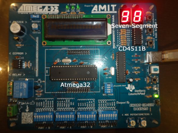
Seven Segment Display operation using Atmega32 and CD4511B
Seven segment display is a frequently used device found in several applications such as queuing systems, some types of clocks and calculators. So in this article, we explain how to Interface a 7 Segment Display to the AVR Atmega32 MCU and get it working.
Note: We have published several other interfacing tutorials of 7 segment displays like Interfacing 7 segment to 8051, Interfacing Arduino to 7 Segment Display, and a Proteus Tutorial on 7 Segment display.
Let’s first have a look on the seven-segment display and its pinout.
The Seven-segment consists of 7 LEDs arranged in a way that allows constructing a display of the numbers of (0-9). It has 10 pins assigned as follows:
- 7 pins act as the Vcc for the 7 LEDs (1 pin for each LED, assuming that we are dealing with common cathode seven segment display)
- 1 pin is the VCC for decimal point display at the lower right corner.
- 2 pins represent a common ground to all the LEDs.
There are 2 types of seven-segment, that are “common anode” and “common cathode”. In common anode seven segment, VCC is common for all the LEDs and each has a different pin for the low voltage (that is ground). In the case of a common cathode, all LEDs have a common ground and each has a different pin for the high voltage (Vcc). In this tutorial, we will be using a common cathode 7 Segment display.
Interfacing 7 Segment Display with AVR Atmega32:
The straightforward way to do that is to connect each pin from the seven-segment to a pin on the MCU and use the software to control the LEDs lighting and display the numbers we want. However, this way is not efficient as it wastes a lot of valuable MCU pins. Imagine that you want to connect 2 seven-segment devices to display the numbers (0-99), in this case, you will need to use 14 pins of the MCU I/O pins which may leave you in a shortage of pins for other external peripherals.
Fortunately, there is a better way to do it, using the CD4511B IC (BCD to 7 Segment Decoder), shown in the below picture.
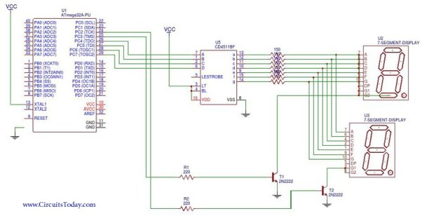
This is an easy to use IC that takes the number you want to display as an input in BCD (Binary Coded Decimal) format and outputs the 7 bits needed to illuminate the seven-segment with the desired number. The below diagram clarifies the input and output to the CD4511B.
Read more: Interface 7 Segment Display to AVR Atmega32 using CD4511B
- What types of seven-segment displays are there?
There are common anode and common cathode seven-segment displays. - Which type is used in this tutorial?
The tutorial uses a common cathode seven-segment display. - How many pins does a seven-segment display have?
It has 10 pins: seven segment pins, one decimal point pin, and two common ground pins (for common cathode). - Can I directly connect a seven-segment display to the Atmega32?
Yes, but directly connecting each segment to MCU pins wastes many I/O pins. - What IC can reduce MCU pin usage for driving a seven-segment?
The CD4511B BCD to 7-segment decoder IC is used to reduce MCU pin usage. - How does the CD4511B simplify interfacing?
CD4511B accepts BCD input and outputs the seven segment lines, so the MCU only needs to provide BCD signals instead of individual segment controls. - What numeric range can be displayed with a single seven-segment driven by CD4511B?
A single seven-segment driven by CD4511B can display digits 0 through 9. - Why is using CD4511B better for multiple displays?
Because it reduces the number of MCU pins required compared to directly driving each segment, making it more efficient for multiple displays.