Summary of Interfacing 16×2 LCD with Atmega16 AVR Microcontroller in 4-Bit Mode
This article details how to interface a 16x2 LCD display with an Atmega16 AVR microcontroller using C programming in Atmel Studio. It covers hardware setup, circuit connections, and software logic for displaying text in 4-bit mode without external libraries.
Parts used in the Interfacing 16x2 LCD with Atmega16:
- Atmega16 Microcontroller
- 16x2 LCD Module
- Jumpers
- Breadboard
- USBASP Programmer
- 10k POT (Potentiometer)
- Atmel Studio 7.0 Software
Display is the necessary part of any machine whether it is any home appliance or industrial machines. Display not only shows the control options to operate the machine but also shows the status and output of the task performed by that machine. There are many types of displays used in electronics like 7-segment display, 16×2 LCD display, TFT touch screen display, OLED display etc.
16×2 LCD display is the most basic display module and also used in some small electronics equipment like calculator, digital meter etc. We have done lot of projects using 16×2 LCD including the basic interfacing with other microcontrollers:
- LCD Interfacing with 8051 Microcontroller
- Interfacing LCD with ATmega32 Microcontroller
- LCD Interfacing with PIC Microcontroller
- Interfacing 16×2 LCD with Arduino
- 16×2 LCD Interfacing with Raspberry Pi using Python
In this tutorial, we will see how to interface a 16×2 LCD with Atmega16 AVR microcontroller and display a simple welcome message.
Components Required
- Atmega16
- 16×2 LCD Module
- Jumpers
- Breadboard

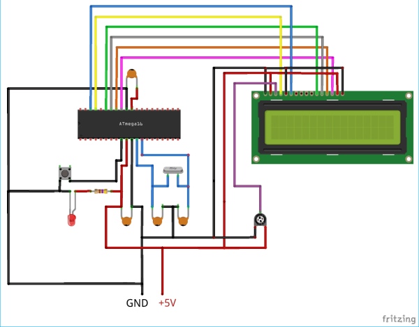
Circuit Diagram
Programming Atmega16 for 16×2 LCD Display
Programming doesn’t require any external libraries. Here the Atmega16 is programmed using USBASP and Atmel Studio7.0. Complete Program and Working Video is given at the end of the project, just upload the program in Atmega16 and rotate 10k POT to adjust the brightness of LCD.
Initially define the CPU Frequency and include the necessary libraries which comes with Atmel Studio Package such as <avr/io.h> for accessing IO pins and <util/delay.h> for generating delay in the program.
<util/d#define F_CPU 16000000UL
#include <avr/io.h>
#include <util/delay.h>
Define RS and EN pin of LCD in the program. The RS Pins is used to select the data and command register. The enable pin latches the data.
#define en PA3
#define rs PA2
Also define that which PORT of Atmega16 will be used to interface LCD. Here, the PORTA is used.
#define lcdDirection  DDRA
#define lcdPort PORTA
Next step is to construct a function which will accept a command by passing a parameter. There are many LCD HEX Commands. The Hex Commands are used to define the function of LCD. Since we are using the 4-bit Mode of LCD, the byte (8-bit) will be sent in two packets. The one packets will be Upper Nibble (4-bit) and other packet will be Lower Nibble (4-bit).
void lcdCommand( unsigned char commands )
{
lcdPort = (lcdPort & 0x0F) | (commands & 0xF0);
            lcdPort &= ~ (1<<rs);
            lcdPort |= (1<<en);
            _delay_us(1);
            lcdPort &= ~ (1<<en);
            _delay_us(200);
            lcdPort = (lcdPort & 0x0F) | (commands << 4);
            lcdPort |= (1<<en);
            _delay_us(1);
            lcdPort &= ~ (1<<en);
            _delay_ms(2);
}
The next step would be accepting the characters and latching it to the port of LCD. The characters received is then sent to the LCD nibble by nibble. The Function takes the character using pass by parameter and then takes the upper and lower nibble. The ‘rs’ pin is set to high for data register and then a rising pulse is sent to latch the data. Similarly the lower nibble in sent by changing the value of enable and sending the rising pulse for enable.
void lcdChar( unsigned char string )
{
            lcdPort = (lcdPort & 0x0F) | (string & 0xF0);
            lcdPort |= (1<<rs);
            lcdPort|= (1<<en);
            _delay_us(1);
            lcdPort &= ~ (1<<en);
            _delay_us(200);
            lcdPort = (lcdPort & 0x0F) | (string << 4);
            lcdPort |= (1<<en);
            _delay_us(1);
            lcdPort &= ~ (1<<en);
            _delay_ms(2);
}
This function just converts the character into string and can be used in the program later where writing string is needed.
void lcdString (char *str)
{
            int j;
            for(j=0;str[j]!=0;j++)
            {
                        lcdChar (str[j]);
            }
}
Now a function is written just to clear the screen. You just need to send the command 01 in HEX and then just set the cursor to initial position.
void lcdClear()
{
            lcdCommand (0x01);
            _delay_ms(2);
            lcdCommand (0x80);
}
Now in the main function, the LCD is initialized. Initially set the PORT direction for LCD to interface. Here, the PORT is set as OUTPUT so set FF.
lcdDirection = 0xFF;
_delay_ms(20)
Then set the LCD in the 4-bit mode by sending 02 in hex. Also send 28 in hex to set it in the 2 line, 15×7 matrix pixels in 4-bit mode.
lcdCommand(0x02);
lcdCommand(0x28);
The command 0c and 06 is used to control cursor position. And finally just clear the screen by sending 01 in hex. This will finish the initialization of LCD.
lcdCommand(0x0c);
lcdCommand(0x06);
lcdCommand(0x01);
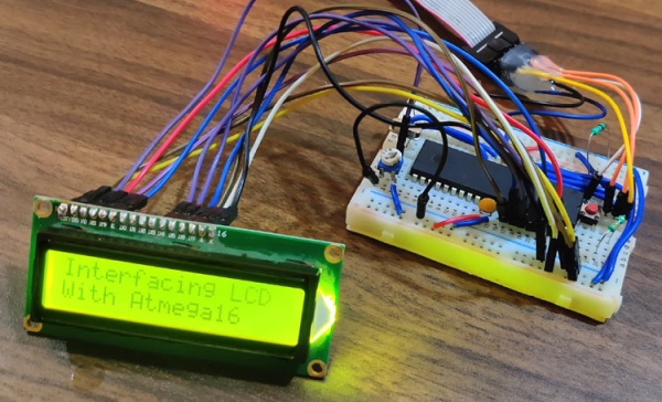
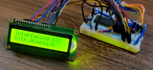
After initialization is finished just test the LCD by sending a string. Here we are sending a String “Interfacing LCD” in the 1st row.
lcdString("Interfacing LCD");
Then move the cursor to the next row by sending the command c0 in hex. And finally on this position, write the string “With Atmega16″.
lcdCommand(0xC0);
lcdString("With Atmega16");
This finishes the complete tutorial on Interfacing a 16×2 LCD with Atmega16. Note that if you don’t get any image or pixels then either check your wiring according to code and circuit diagram or change the value of the POT attached to V0 pin of LCD. If you have any doubt or suggestion then you can reach us to either by writing to our forum or comment below.
Code
/*
LCD16x2 4 bit ATmega16 interface
CircuitDigest(www.circuitdigest.com)
*/
define F_CPU 16000000UL // Define CPU Frequency here it 16MHz
include // Include AVR std. library file
include // Include Delay header file
define en PA3 // Define Enable pin
define rs PA2 // Define Register Select pin
define lcdDirection DDRA // Define LCD data direction port
define lcdPort PORTA //Define LCD data port
void lcdCommand( unsigned char commands ) // commands will be sent from this function
{
lcdPort = (lcdPort & 0x0F) | (commands & 0xF0); // send upper nibble of 8 bit
lcdPort &= ~ (1<<rs); // rs=0 i.e select command reg
lcdPort |= (1<<en); // give high pulse to enable pin
_delay_us(1);
lcdPort &= ~ (1<<en); // give low pulse to enable pin
_delay_us(200);
lcdPort = (lcdPort & 0x0F) | (commands << 4); // sending lower nibble of 8 bit i.e 1byte
lcdPort |= (1<<en); // give high pulse to enable pin
_delay_us(1);
lcdPort &= ~ (1<<en); // give low pulse to enable pin
_delay_ms(2);
}
void lcdChar( unsigned char string )
{
lcdPort = (lcdPort & 0x0F) | (string & 0xF0); // send upper nibble
lcdPort |= (1<<rs); // rs=1 i.e select data reg
lcdPort|= (1<<en); // give high pulse to enable pin
_delay_us(1);
lcdPort &= ~ (1<<en); // give low pulse to enable pin
_delay_us(200);
lcdPort = (lcdPort & 0x0F) | (string << 4); //send lower nibble
lcdPort |= (1<<en); // give high pulse to enable pin
_delay_us(1);
lcdPort &= ~ (1<<en); // give low pulse to enable pin
_delay_ms(2);
}
void lcdString (char *str) // convert char to string fucntion
{
int j;
for(j=0;str[j]!=0;j++)
{
lcdChar (str[j]);
}
}
void lcdClear()
{
lcdCommand (0x01); // send hex 01 to Clear display
_delay_ms(2);
lcdCommand (0x80); // send hex 80 to Cursor at home position
}
int main()
{
// start Initializing 16×2 LCD
lcdDirection = 0xFF; // set LCD port direction in output
_delay_ms(20); // keep LCD Power ON delay >15ms always
lcdCommand(0x02); // send for 4 bit initialization of LCD
lcdCommand(0x28); // 2 line, 5*7 matrix in 4-bit mode
lcdCommand(0x0c); // Display on cursor off
lcdCommand(0x06); // take curson to next position (shift cursor to right)
lcdCommand(0x01); // Clear display screen
_delay_ms(2); //little delay
lcdString(“Interfacing LCD”); // Write string on 1st row of 16×2 LCD
lcdCommand(0xC0); // move to 2nd row
lcdString(“With Atmega16”); // write string on second line
}
Video
Source: Interfacing 16×2 LCD with Atmega16 AVR Microcontroller in 4-Bit Mode
- How is the LCD programmed?
The Atmega16 is programmed using USBASP and Atmel Studio 7.0 without requiring external libraries. - Which pins are defined for RS and EN?
The RS pin is defined as PA2 and the EN pin is defined as PA3. - In which mode is the LCD configured?
The tutorial configures the LCD in 4-bit mode using hex commands 02 and 28. - What library files are included in the code?
The code includes avr/io.h for accessing IO pins and util/delay.h for generating delays. - How do you clear the screen?
You send the hex command 01 to clear the display and 80 to set the cursor to the initial position. - What string is displayed on the first row?
The string Interfacing LCD is written on the first row of the display. - How do you adjust the LCD brightness?
You rotate the 10k POT attached to the V0 pin of the LCD to adjust the brightness. - What happens if no image appears on the display?
You should check your wiring against the code and circuit diagram or change the POT value.