Summary of Interfacing 8051 Microcontroller With Lcd in 4-bit Mode
This tutorial explains interfacing an LCD 16x2 with an 8051 microcontroller in 4-bit mode to save GPIO pins. It details the required software (Keil, Proteus, Flash Magic) and hardware components for both simulation and physical implementation. The article describes the circuit logic, explaining how data is split into nibbles using bitwise operations before transmission to the display.
Parts used in the Interfacing 8051 Microcontroller With Lcd in 4-bit Mode:
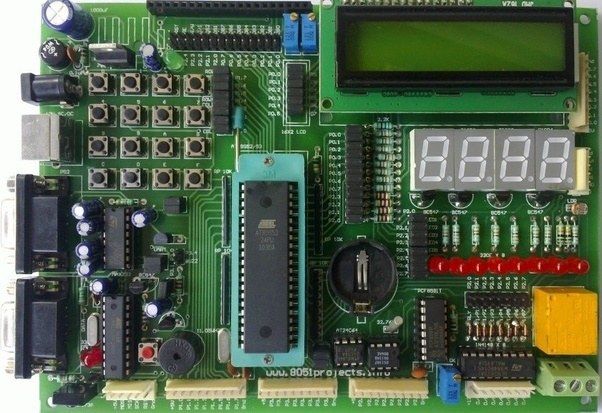
- 8051 Development board
- LCD 16*2
- USB to UART converter
- 9Pin D type male Connecter For Rs232 O/p
- Jumper Wires
In this tutorial we are going to tell you about how we can interface lcd with 8051 in 4-bit mode.

Step 1: Software Used:
As we are showing proteus simulation so FOR CODING AND SIMULATION YOU REQUIRED:
1 Keil uvision: Their are lots of product from keil. so you will be required c51 compiler. You can download that software from here
2 Proteus Software for simulation: This is the software to show simulation. You will get lot of information to download this software.
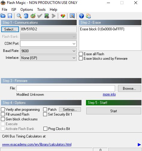
If you are doing it in hardware then you would require one software that is flash magic to upload the code in your hardware. Remember flash magic is developed by nxp. So you can not upload all 8051 family microcontroleer through this software. So Philips based controller only you can upload.
Step 2: Components Required:
Here in our demo video we are using proteus simulation but definetly if you are doing it in your hardware you will be required these components for this project:
8051 Development board: So if you have this board it will be better so that you can easily upload the code by yourself.
LCD 16*2: This is 16*2 lcd . In this lcd we have 16 pins.
USB to UART converter: This is 9Pin D type male Connecter For Rs232 O/p Jumper Wires
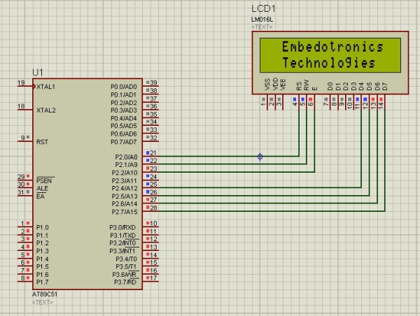
Step 3: Circuit Diagram:
Step 4: Working Principle of This Project:
As in 8 bit we need to connect all 8 data pins of lcd to microcontroller. So total 11 pins of microcntroller we need to use as we have 3 control pins(rs,rw,e) in lcd as well. So the advantage of lcd in 4 bit is that we are saving 4 pins of microcontroller so that we can use these pins for other work.
Now the working principle of code is very simple. First you just download the code.
Ok, Now I will take one function from the code and will tell how that command or data lcd is receiving. In our code first command instruction is
cmd(0x28);
So now it will go to it’s definition
void cmd(unsigned char a)
{
unsigned char x;
x=a&0xf0;
cmd1(x);
x=(a<<4)&0xf0;
cmd1(x);
}
so in the above function you can see a is nothing but 0x28. Now through x=a&0xf0, lower nibble will become 0. as we are using AND operator with 0xf0. So in higher nibble only we have data, then through cmd1(x) we are sending 0x20 to port 2 and lcd is connected to higher bits of port 2 so it will receive 2, now immediately we need to send the next nibble which is nothing but 0x8. So for that you can see in the function x=(a<<4)&0xf0, we are shifting a value 4 times and then we are using and operation with 0xf0.
So just understand this
a<<4 is nothing but 0x28<<4, which means 00101000<<4, So we will get
10000000 and we are anding with 0xf0 and we will get 0b10000000 which is 0x80, and from next function cmd1(x) we are sending that data to lcd and now it will receive 0x80 so this way we have sent the whole data 0x28.
So the same way every command and data lcd will receive.
I hope you understand this. Still you can checkout the video which is in the next step. The whole project description is given in that video.
Step 5: Code and Video
You can get the source code from our GitHub Link
The whole project description is given in the above video.
If you have any doubt regarding this project feel free to comment us below. And if you want to learn more about embedded system you can visit our youtube channel
Please visit and like our Facebook Page for frequent updates.
This channel just now we have started but daily you will get some videos regarding embedded system and IoT.
Source: Interfacing 8051 Microcontroller With Lcd in 4-bit Mode
- What software is required for coding and simulation?
You need Keil uvision with the c51 compiler and Proteus Software for simulation. - Can I use Flash Magic for all 8051 family microcontrollers?
No, Flash Magic only works for Philips based controllers within the 8051 family. - How many pins of the microcontroller are saved by using 4-bit mode?
Using 4-bit mode saves 4 pins of the microcontroller compared to 8-bit mode. - How does the code send the command 0x28 to the LCD?
The code sends the higher nibble first, then shifts the value left by 4 bits to send the lower nibble. - Which function definition handles sending commands in the code?
The void cmd(unsigned char a) function handles receiving commands or data. - Where can I find the source code for this project?
The source code is available via the GitHub Link provided in the article. - What is the advantage of connecting the LCD in 4-bit mode?
The advantage is saving 4 pins of the microcontroller so they can be used for other work. - How many control pins are needed in the LCD interface?
Total 11 pins of the microcontroller are used including 3 control pins rs, rw, and e.