Summary of Interfacing Servo Motor with Atmega32 Microcontroller
This article explains how to control a hobby servo motor's angular position (0-180°) using an Atmega32 microcontroller. It details the use of Pulse Width Modulation (PWM) signals, where pulse widths between 1ms and 2ms determine specific angles. The project circuit includes an 8MHz crystal with stabilization capacitors and a Power-On Reset circuit, while the software generates precise delays to rotate the motor to 0, 90, and 180 degrees in a continuous loop.
Parts used in the Servo Motor Control Project:
- Servo Motor (0-180° range)
- Atmega32 Microcontroller
- 8 MHz Crystal
- 22pF Capacitors (x2)
- 10KΩ Resistor
- 10μF Capacitor
- Red Power Wire
- Black Ground Wire
- Control Signal Wire
A Servo Motor is a type of DC Motor that incorporates error sensing negative feedback to precisely regulate the angular position of its shaft. Unlike standard DC Motors, servo motors do not rotate continuously but instead perform controlled angular rotations, such as 0-90° or 0-180°. While Stepper Motors can also achieve accurate angular rotations, Servo Motors are favored for applications involving angular motion, such as robotic arms. This preference arises from the simplicity of controlling Servo Motors, the absence of additional drivers required as with stepper motors, and the capability for exclusive angular motion.
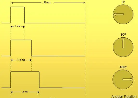
The operation of a Hobby Servo Motor is straightforward, requiring just three wires. Two of these wires, typically Red and Black, supply power, while the third wire delivers control signals. Control signals are generated using Pulse Width Modulated (PWM) waves, and the angular position is determined by the width of the pulse received at the control input. In this tutorial, we are employing a servo motor with a rotation range from 0-180°, and the angular position can be managed by adjusting the pulse width within the range of 1ms to 2ms.
Please be aware that you should consult the datasheet of your specific Servo Motor before implementing the program provided in this tutorial, as the angular range and control pulse width may vary among different servo motors.
Circuit Diagram
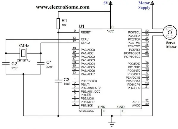
An 8 MHz crystal is employed to supply the necessary clock signal for the Atmega32 Microcontroller, with the operation of the crystal being stabilized through the use of 22pF capacitors. Additionally, a 10KΩ resistor and a 10μF capacitor are utilized to deliver the necessary Power-On Reset (POR) to the microcontroller. The control of the servo motor is linked to the initial pin of PORTC (RC0), which has been designated as an output pin within the program.
Program
#ifndef F_CPU
#define F_CPU 8000000UL // 8 MHz clock speed
#endif
#include <avr/io.h>
#include <util/delay.h>
int main(void)
{
DDRC = 0x01; //Makes RC0 output pin
PORTC = 0x00;
while(1)
{
//Rotate Motor to 0 degree
PORTC = 0x01;
_delay_us(1000);
PORTC = 0x00;
_delay_ms(2000);
//Rotate Motor to 90 degree
PORTC = 0x01;
_delay_us(1500);
PORTC = 0x00;
_delay_ms(2000);
//Rotate Motor to 180 degree
PORTC = 0x01;
_delay_us(2000);
PORTC = 0x00;
_delay_ms(2000);
}
}
Source: Interfacing Servo Motor with Atmega32 Microcontroller
- How does a servo motor differ from a standard DC motor?
Servo motors do not rotate continuously but perform controlled angular rotations like 0-90° or 0-180°. - What determines the angular position of the servo motor?
The width of the Pulse Width Modulated (PWM) pulse received at the control input determines the angle. - Which pins are used for power on a hobby servo motor?
The Red and Black wires supply power to the motor. - What is the pulse width range for controlling a 0-180° servo?
The angular position is managed by adjusting the pulse width within the range of 1ms to 2ms. - Why are servo motors preferred over stepper motors for robotic arms?
Servo motors are favored due to simpler control, no need for additional drivers, and exclusive angular motion capability. - What component supplies the clock signal for the Atmega32 microcontroller?
An 8 MHz crystal is employed to supply the necessary clock signal. - How is the operation of the crystal stabilized?
The crystal operation is stabilized through the use of two 22pF capacitors. - Which microcontroller pin controls the servo motor in this program?
The control is linked to the initial pin of PORTC (RC0). - What should users check before implementing the provided program?
Users should consult the datasheet of their specific Servo Motor as ranges may vary. - What function does the 10KΩ resistor serve in the circuit?
It is utilized along with a 10μF capacitor to deliver the necessary Power-On Reset to the microcontroller.