Summary of Interfacing Stepper Motor with AVR Microcontroller Atmega16
Summary: This tutorial shows how to interface a 28BYJ-48 stepper motor with an Atmega16 AVR microcontroller using ULN2003 and L293D driver modules. It covers required components, pin mappings (PORTA to driver inputs and motor coils), circuit connections, half/full-step sequences, example AVR C code, and programming the Atmega16 via USBASP and Atmel Studio 7.0. The example rotates the motor clockwise and counterclockwise and explains changing speed by adjusting delay between steps.
Parts used in the 28BYJ-48 Stepper Motor with Atmega16:
- Stepper Motor (28BYJ-48)
- ULN2003 Module or L293D Motor Driver
- Atmega16 Microcontroller IC
- 16 MHz Crystal Oscillator
- Two 100 nF Capacitors
- Two 22 pF Capacitors
- Push Button
- Jumper Wires
- Breadboard
- USBASP v2.0 programmer
- LED (any color)
Stepper Motors are DC brushless motors which can rotate from 00 to 3600 in steps. Stepper motor uses electronic signals to rotate the motor in steps and each signal rotates the shaft in fixed increment (one step). The rotation angel is controlled by applying certain sequence of signals. Unlike Servo Motor, stepper motors can be driven by using GPIO pins of microcontroller rather than PWM pins and can rotate in (+3600) and (-3600). The order of signals decides the clockwise and counter clockwise direction of stepper motor. To control the speed of the motor, we just need to change the rate of control signals applied. The stepper motors rotates in steps. There are several modes of steps to operate Stepper Motor such as full step, half step and microstep. To know more about the basics, theory and working principle of stepper motor, follow the link.
We previously interfaced Stepper Motor with many Microcontrollers:
- Interfacing Stepper Motor with ARM7-LPC2148
- Interfacing Stepper Motor with Arduino Uno
- Interfacing Stepper Motor with MSP430G2
- Interfacing Stepper Motor with STM32F103C8
- Interfacing Stepper Motor with PIC Microcontroller
- Interfacing Stepper Motor with 8051 Microcontroller
- Interfacing Stepper Motor with Raspberry Pi
In this tutorial we will interface 28BYJ-48 Stepper Motor with Atmega16 AVR Microcontroller using Atmel Studio 7.0. The stepper motor is rated to work in 5V. We will be interfacing the stepper motor with both the motor drivers i.e. ULN2003 and L293. Both will be driven by 5V supply. In order to simplify the interfacing we are using prebuild module of both motor drivers. You can also use ULN2003 and L293D standalone IC’s. The number of wires and jumpers can be more, so just be careful while connecting all the connections.
Components Required
- Stepper Motor(28BYJ-48)
- ULN2003 Module/L293D Motor Driver
- Atmega16 Microcontroller IC
- 16Mhz Crystal Oscillator
- Two 100nF Capacitors
- Two 22pF Capacitors
- Push Button
- Jumper Wires
- Breadboard
- USBASP v2.0
- Led(Any Color)
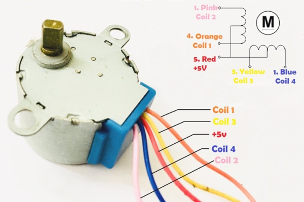
Pin Description of Stepper Motor
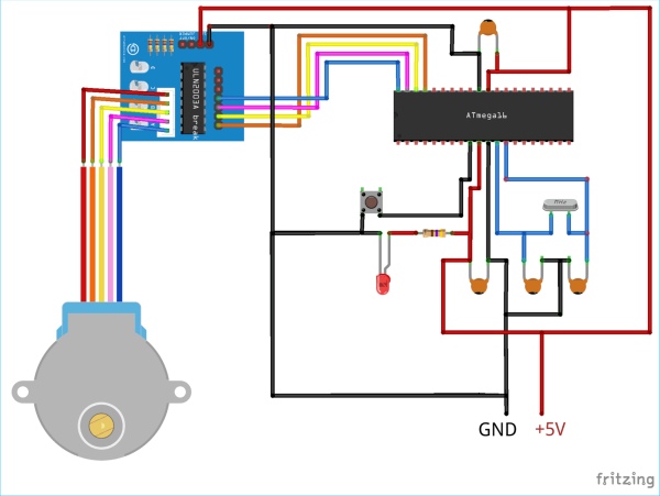
Circuit Diagram for Stepper Motor Control using ULN2003 Module
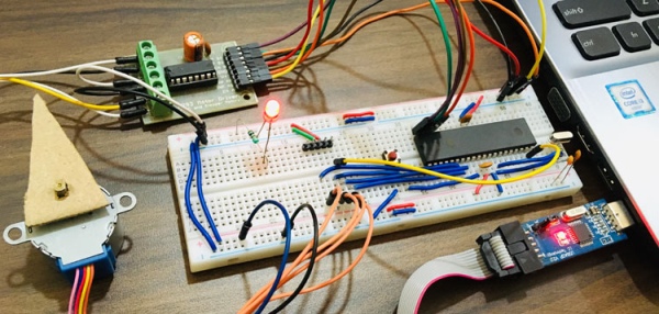
Connect all the components as shown in the diagram below when using ULN2003. Similarly we will be interfacing it using L293D in next step. We are using PORTA of Atmega16 to interface stepper motor for both the motor drivers. There is no need to connect the 5V pin of stepper motor. Only the coil pins are required to move the stepper motor. The pin order is very important to drive stepper motor as the energizing of the coils should be in order to attain steps. Four inputs of ULN2003 and four outputs of ULN2003 are used in this project. The inputs will be connected to PORTA pins and outputs will be connected to Stepper Motor Signal pins. Also, connect one push button in Reset pin for resetting Atmega16 whenever required. Connect Atmega16 with proper crystal oscillator circuit. All the system will be powered by 5V supply.
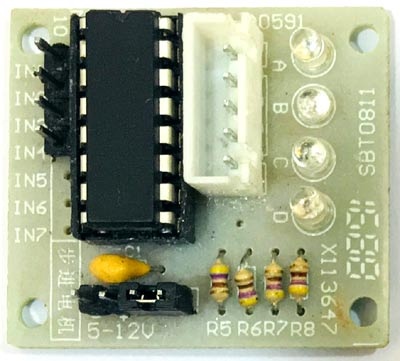
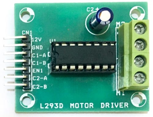
Below is the actual Picture of ULN2003 Motor Driver Module:
Below we have given Atmega16 pin connections with ULN2003 and L293D to rotate the stepper motor. Interfacing stepper motor with L293D module is explained in later section, remember that only one module either ULN2003 or L293D is required for stepper motor control.
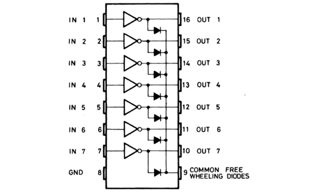
The pin connections for INPUT are as follows:
| Atmega16 | ULN2003 | L293D |
| A0 | IN1(PIN1) | IN1(PIN2) |
| A1 | IN2(PIN2) | IN2(PIN7) |
| A2 | IN3(PIN3) | IN3(PIN10) |
| A3 | IN4(PIN4) | IN4(PIN15) |
The pin connections for OUTPUT are as follows:
| Stepper Motor | ULN2003 | L293D |
| Orange | OUT1(PIN16) | OUT1(PIN3) |
| Yellow | OUT2(PIN15) | OUT2(PIN6) |
| Pink | OUT3(PIN14) | OUT3(PIN11) |
| Blue | OUT4(PIN13) | OUT4(PIN14) |
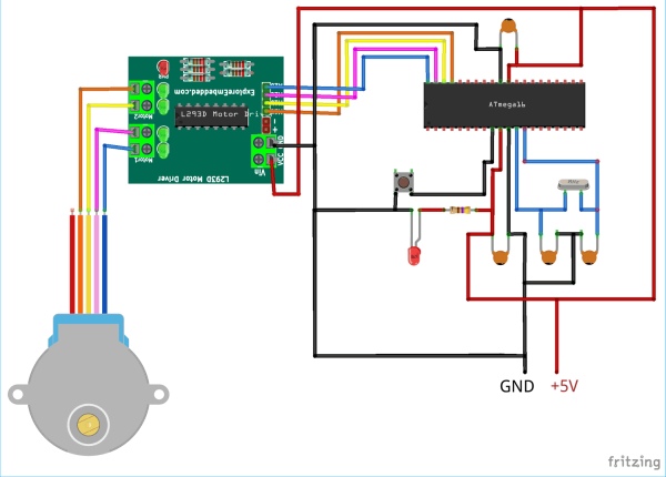
Circuit Diagram for Stepper Motor control using L293D Module:
Controlling Stepper Motor with AVR ATmega16
As already told unlike Servo Motor, Stepper motors need external drivers e.g. ULN2003 or L293D motor driver. So just connect the Circuit as above and upload the main.c program given at the end.
The sketch demonstrates the stepper motor rotating in both sides i.e. clockwise and counter clockwise direction. If you want to rotate the stepper in one direction simply comment out another direction’s code lines in the sketch.
Complete AVR code for controlling Stepper Motor is given below. Code is simple and can be understood easily. Two codes are given below, one for rotating stepper motor with ULN2003 and second with L293D module.
Connect your USBASP v2.0 and follow the instructions in this link to program Atmega16 AVR Microcontroller using USBASP and Atmel Studio 7.0. Just build the sketch and upload using external toolchain.
Complete code with Demonstration Video is given below.
Code
define F_CPU 16000000UL /* Define CPU Frequency 1MHz */
include /* Include AVR std. library file */
include /* Include delay header file */
int main(void)
{
//int period;
DDRA = 0x0F; /* Make PORTA lower pins as output / int period = 6; / Set period in between two steps */
while (1)
{
/* Rotate Stepper Motor clockwise with Half step sequence / for(int i=0;i<50;i++) { PORTA = 0x09; _delay_ms(period); PORTA = 0x08; _delay_ms(period); PORTA = 0x0C; _delay_ms(period); PORTA = 0x04; _delay_ms(period); PORTA = 0x06; _delay_ms(period); PORTA = 0x02; _delay_ms(period); PORTA = 0x03; _delay_ms(period); PORTA = 0x01; _delay_ms(period); } PORTA = 0x09; / Last step to initial position */
_delay_ms(period);
_delay_ms(1000);
/* Rotate Stepper Motor Anticlockwise with Full step sequence */
for(int i=0;i<50;i++)
{
PORTA = 0x01;
_delay_ms(period);
PORTA = 0x03;
_delay_ms(period);
PORTA = 0x02;
_delay_ms(period);
PORTA = 0x06;
_delay_ms(period);
PORTA = 0x04;
_delay_ms(period);
PORTA = 0x0C;
_delay_ms(period);
PORTA = 0x08;
_delay_ms(period);
PORTA = 0x09;
_delay_ms(period);
}
PORTA = 0x09;
_delay_ms(period);
_delay_ms(1000);
}
}
Video
Source: Interfacing Stepper Motor with AVR Microcontroller Atmega16
- What motor is used in the project?
The project uses a 28BYJ-48 stepper motor. - Which drivers can be used to drive the stepper motor?
The tutorial uses either a ULN2003 module or an L293D motor driver module. - Which microcontroller port is used to interface the motor?
PORTA of the Atmega16 is used to interface the stepper motor inputs. - Do I need to connect the 5V pin of the stepper motor module?
The article says there is no need to connect the 5V pin of the stepper motor when only coil pins are used to move the motor. - How is direction controlled in the code?
Direction is controlled by the order of control signals; the code includes sequences for clockwise and anticlockwise rotation. - How is speed controlled?
Speed is controlled by changing the delay period between control signal steps in the code. - How to program the Atmega16 for this project?
Program the Atmega16 using USBASP v2.0 and Atmel Studio 7.0 following the provided instructions. - What stepping modes are mentioned?
The article mentions full step, half step, and microstep modes, and demonstrates half and full step sequences in the code. - Can I use standalone ULN2003 or L293D ICs instead of modules?
Yes, you can use ULN2003 and L293D standalone ICs, though wiring will be more complex. - What should be connected to the Reset pin?
A push button is connected to the Reset pin to reset Atmega16 when required.