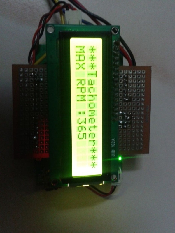
Summary of Linkit One- Portable Tachometer Noncontact
This article details a DIY non-contact tachometer project using a Linkit One board and an IR sensor. The device measures rotational speed by detecting light interruptions from a rotating object, displaying results on a 16x2 LCD screen. The build involves assembling a sensor probe with an IR LED and photodiode, creating a portable shield for the microcontroller, and integrating a battery for mobility.
Parts used in Portable Tachometer:
- Linkit one Board with Battery
- Infra red LED and Photo Diode
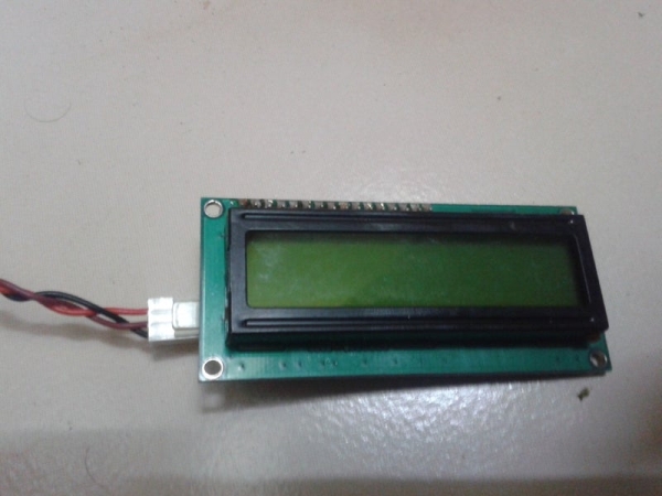
- 16X2 Serial LCD display
- 270 ohms Resister
- 33K Resister
- 1K Trim pot
- PCB push button
- Double Side Tape
- Wires, Soldering Iron lead and Paste
- Old Sketch pen
We use tachometer in our industry. So Like to make some tachometer to check it in home with available resource.
Step 1: Materails Required
1) Linkit one Board with Battery.
2) Infra red LED and Photo Diode – 1no.
3) 16X2 Serial LCD display.
4) 270 ohms Resister – 1No.
5) 33K Resister – 1No.
6) 1K Trim pot.
7) PCB puch button 1 No
8) Double Side Tape.
9) Wires, Soldering Iron lead and Paste
10) old Sketch pen.
Step 2: Sensor Circuit
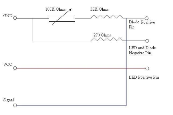
1) Above is the sensor Circuit Diagram.
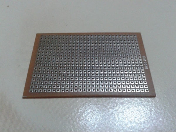
2) Cut a small piece of PCB and Soldered the Components as Per diagram.
3) Cut the Sketch Pen body for two smalls tubes.
4) use it to separate the IR LED and Photo Diode.
5) Fix it using Hot Glue Gun.
6) Another Small Circuit For Digital Input using a Push Button and 220 Ohms Resister.
7) Solder a Female PCB connector in the Sensor board.
8) Solder a Male PCB connector in the Switch Board.
9) Solder four wires VCC, GND, Sensor Signal, Push Button Wire in the Sensor PCB.
10) Join the Male connector to Sensor Board Female Connector.
Step 3: Make a Shield
1) Plug in male connector to the Link it one (to required pins only, For my future use i solder all pins).
2) Join Plain PCB Over it.
3) Solder the pins.
4) Solder the sensor pin wires as follows
a ) Black – GND
b) Red – VCC 5V
c) Blue – A0 Analog input
d) Yellow – 12 Digital Input
5) Solder the Serial LCD Display
a) Black – GND
b) Brown – VCC 5V
c) Red – 1 Tx of the Serial1.
6) Connect the Battery.
All done in circuit part
Step 4: Make It Portable
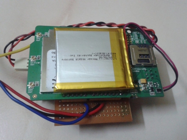
Using double Side Sticker Paste the Battery below the Linkit one board. Paste LCD above the PCB over Linkit one Board. Now u have indicator and a sensor probe.
Source: Linkit One- Portable Tachometer Noncontact
-
What materials are required to build this tachometer?
You need a Linkit one Board, IR LED, Photo Diode, 16X2 Serial LCD, resistors, trim pot, push button, double side tape, wires, soldering tools, and an old sketch pen. -
How do you separate the IR LED and Photo Diode?
Cut the body of an old sketch pen into two small tubes and use them to separate the components before fixing them with a hot glue gun. -
Which pins on the Linkit One board connect to the sensor?
The sensor connects via VCC to Red wire, GND to Black wire, Analog input A0 to Blue wire, and Digital Input 12 to Yellow wire. -
Can this device be made portable?
Yes, you can paste the battery below the Linkit One board and the LCD above the PCB to create a portable indicator and sensor probe. -
What is the purpose of the push button circuit?
A small circuit using a push button and a 220 Ohms resistor is created for digital input functionality. -
How are the LCD display connections defined?
The LCD connects with Black to GND, Brown to VCC 5V, and Red to the Tx pin of Serial1.