Summary of Managing DC Motor Speed and Direction with AVR Microcontrollers (Part 20/46)
This project demonstrates how to control the speed and direction of a 12V DC motor using an ATmega32 microcontroller and Pulse Width Modulation (PWM). The system utilizes push buttons for user input to start, stop, reverse, and adjust motor velocity, while LEDs provide visual feedback on operation status. The L293D driver chip manages the high current required by the motor, interfacing with the low-power microcontroller to execute precise motion control suitable for robotics, industrial, and defense applications.
Parts used in the AVR ATMega32 based DC Motor Controller:
- ATmega32 Microcontroller
- L293D Motor Driver Chip
- 12V 500 RPM DC Series Motor
- Five Push Buttons (SW1 to SW5)
- Six LEDs (Red, Green, Blue, Orange)
- Current-limiting Resistors
- External Pull-up Resistors
- 16 MHz Crystal Oscillator
- Two 22 pF Capacitors
- 5V Vcc Power Supply
- 12V Motor Power Supply
Managing the speed and direction of a DC motor holds significant importance across various applications:
– In robotic applications, altering the speed and direction is crucial for controlling the movement of robots.
– Industrial scenarios require the ability to adjust the speed and direction of rotating machinery.
– Within domestic settings, regulating the speed of battery-operated portable fans is essential.
– Defense applications often necessitate rotating radar, automatic guns, or tank guns in different directions.
– Communication applications involve tasks such as adjusting dish antenna positions both vertically and horizontally.
Numerous applications demand altering the direction and/or speed of DC motors. The motor’s direction can be controlled by reversing the polarity of the supplied power. To regulate the speed, multiple methods exist, yet the most effective among them is Pulse Width Modulation (PWM). This technique involves adjusting the pulse width, which consequently modifies the average voltage applied to the motor, thereby altering its speed.
This project aims to illustrate the process of adjusting the speed and altering the direction of a simple 12V 500 RPM DC series motor using the AVR microcontroller ATmega32.
System block diagram:
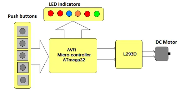
The fundamental components of this system, depicted in the figure, comprise the ATmega32 and the DC motor driver chip L293D. Additionally, the setup requires push buttons for control purposes and LEDs for signaling. Here’s a concise description of each block:
Five push buttons are allocated for executing operations such as initiating, halting, modifying the speed, and altering the direction of the DC motor.
|
Button |
Function |
| Button 1 | Run motor in clockwise direction |
| Button 2 | Run motor in anticlockwise direction |
| Button 3 | Stop motor |
| Button 4 | Increase speed |
| Button 5 | Decrease speed |
L293D chip – this chip takes input from micro controller and drives DC motor. The micro controller output current is not enough to drive DC motor directly. The chip has quad half H bridge drivers. It will provide up to 600 mA current to motor that is enough to drive it.
LED indications – six LEDs are used for different indications
|
LED |
colour |
indication |
|
LED 1 |
red |
Blinks when motor runs in clockwise direction |
|
LED 2 |
green |
Blinks when motor runs in anticlockwise direction |
|
LED 3 |
Blue |
Blinks when speed in increased |
|
LED 4 |
Orange |
Blinks when speed is decreased |
|
LED 5 |
red |
Lits ON when speed limit is maximum |
|
LED 6 |
red |
Lits ON when speed limit is minimum |
The ATmega32, an 8-bit microcontroller based on Advanced RISC architecture, boasts low power consumption and high performance capabilities. It encompasses 32 KB of in-system programmable FLASH memory and comes equipped with various built-in peripherals such as a 10-bit, 8-channel ADC, 4 PWM channels, 1 16-bit, and 2 8-bit timers/counters, USART, SPI, IIC, among others. In this particular system, the ATmega32 executes several functions:
– Continuously scans push buttons to gather user input
– Provides diverse indications using LEDs
– Controls the operation (start/stop) of a DC motor
– Modifies the motor’s direction or speed
The circuit comprises the ATmega32, L293D, and a few discrete components including LEDs, resistors, capacitors, and push buttons:
– Five push buttons, labeled as SW1 to SW5, are linked to PORTA pins PA0 to PA4. Additionally, all port pins are pulled high via external pull-up resistors, as illustrated.
– Four LEDs, identified as LED1 to LED4, are connected to PORTD pins PD0 to PD3 using current-limiting resistors.
– PORTC pins PC0 and PC1 are connected to the input of the L293D chip. Two LEDs, labeled as LED5 and LED6, are also linked to these pins via current-limiting resistors.
– The DC motor is connected to the output of the L293D chip.
– A 16 MHz crystal, along with two 22 pF capacitors, is connected to the crystal input pins XTAL1 and XTAL2.
– A 5V Vcc supply is connected to the necessary pins of both chips and pull-up resistors.
– An additional 12V supply is allocated to the L293D chip specifically for the motor’s operation.
Working & Programming
System working and operation:
· Initially, the motor remains stationary, and all LEDs are inactive.
· Upon a momentary press of SW1, the motor initiates rotation in a clockwise direction. Simultaneously, the green LED flashes at the frequency of the PWM.
· Subsequently, pressing SW4 or SW5 results in an increase or decrease in the motor’s speed. This adjustment is indicated by LED1 or LED2 blinking accordingly.
· Continued pressing of SW4 or SW5 causes a continuous increase or decrease in speed. Upon reaching the maximum or minimum limit, the corresponding LED3 or LED5 illuminates.
· While the motor rotates clockwise, pressing SW2 immediately prompts a switch to anticlockwise rotation, and vice versa.
· Pressing SW3 halts the motor’s operation.
Program:
AVR microcontrollers possess an integrated capability to produce PWM using internal timers. This feature allows for PWM generation, enabling the adjustment of a DC motor’s speed. However, not all microcontrollers offer this feature. In cases where it’s unavailable, PWM needs to be generated programmatically. In this scenario, PWM is generated using a program written in C language, compiled, and simulated using AVR Studio software. The comprehensive program comprises various functions:
– **Keydly() function:** This function generates a debounce delay of approximately 0.2 seconds required when a key is pressed.
– **Incspeed() function:** Responsible for increasing the width of the pulse supplied to the motor by extending the ON time and reducing the OFF time. It also monitors the maximum speed limit. Upon reaching the maximum speed, LED3 is activated.
– **Decspeed() function:** Decreases the width of the pulse supplied to the motor by reducing the ON time and increasing the OFF time. It also checks for the minimum speed limit. When the minimum speed is reached, LED4 is illuminated.
– **Clockwise() function:** Continuously delivers PWM to the motor to rotate it in a clockwise direction until any button is pressed.
– **Anticlockwise() function:** Provides continuous PWM to rotate the motor in an anticlockwise direction until any button is pressed.
– **Main() function:** Initializes ports as input or output and subsequently scans all buttons in a continuous loop.
Project Source Code
###


#include <avr/io.h>
#include <util/delay.h>
uint16_t ton=5000,toff=5000;
void keydly()                         // key debounce delay
{
   uint8_t i;
   for(i=0;i<7;i++)
  _delay_loop_2(10000);           // delay loop library function
}
void incspeed()                  // increase width of pulse
{
  PORTD = (0<<PD3);            // led indication
  if(toff>1000)               // check for minimum off time
  {
      toff=toff-500;          // if not then decrease off time
    ton=ton+500;              // and increase on time
  }
  if(toff==1000) PORTD = (1<<PD2);
// if max limit is reached - LED on
}
void decspeed()               // decrease width of pulse
{
  PORTD = (0<<PD2);          // led indication
  if(ton>1000)              // check for minimum on time
  {
     toff=toff+500;        // if not then increase off time
     ton=ton-500;         // and decrease on time
  }
  if(ton==1000) PORTD = (1<<PD3);
                            // if min limit is reached – LED off
}
void clockwise()           // rotate motor clockwise
  {
    while(PINA==0xFF)     // till any key is not pressed
    {
          PORTC=0x01;    // apply PWM to motor
          _delay_loop_2(ton);
          PORTC=0x00;
         _delay_loop_2(toff);
  }
 }
void anticlockwise()     // rotate motor anticlockwise
  {
    while(PINA==0xFF)   // till any key is not pressed
    {
          PORTC=0x02;  // apply PWM to motor
          _delay_loop_2(ton);
           PORTC=0x00;
          _delay_loop_2(toff);                                     }
  }
int main(void)
{
    uint8_t r=0,d;        // run and direction flag
    DDRC=0x03;           // initialize ports as input and output
    DDRD=0x0F;
    DDRA=0x00;
    PORTC=0x00;
    PORTD=0x00;
    while(PINA==0xFF);  //wait till any key is pressed
loop:switch(PINA)
            {
            case 0xFE:      // for 1st key                                   keydly();
            r=1;            // set run flag                                  d=0;    clear direction flag for CLK direction
            clockwise(); // start rotating motor clockwise
            break;
            case 0xFD:      // for 2nd key
            keydly();
            r=1;           // set run flag
            d=1;   // set direction flag for ACLK direction
           anticlockwise(); // start rotating motor anticlockwise
              break;
             case 0xFB:       // for 3rd key
             PORTC = 0x00;   // stop motor
             PORTD = 0x00;   // all indications off
             r = 0;         // clear run flag
             Break;
             case 0xF7:      // for 4th key
             PORTD=(1<<PD0);    // blink LED1
              keydly();
              PORTD=(0<<PD0);
              incspeed();               // increase speed
              if(r==1)               // if motor was running
              {
              if(d==0) clockwise();  // keep it running clockwise
              else anticlockwise();       // or anticlockwise
               }
               break;
               case 0xEF:                // for 5th key
               PORTD=(1<<PD1);          // blink LED2
               keydly();
                PORTD=(1<<PD1);
                decspeed();                 // decrease speed                    if(r==1)                 // if motor was running
               {
                 if(d==0) clockwise();       // keep it running
                  else anticlockwise();
                }
                break;
                }                                                    goto loop;
}


###
Project Video
- How is the speed of the DC motor regulated?
The speed is regulated using Pulse Width Modulation (PWM), which adjusts the pulse width to modify the average voltage applied to the motor. - Can the direction of the motor be reversed?
Yes, the direction is controlled by reversing the polarity of the supplied power through specific button inputs. - Which chip is used to drive the DC motor directly?
The L293D chip is used to drive the motor because the microcontroller output current is insufficient for direct driving. - What function does Button 1 perform?
Button 1 initiates the motor rotation in a clockwise direction. - Does pressing Button 4 increase or decrease speed?
Pressing Button 4 increases the speed of the motor. - What indicates that the speed limit is maximum?
LED 5 lights up red when the speed limit reaches its maximum value. - How are push buttons connected to the microcontroller?
The five push buttons are linked to PORTA pins PA0 to PA4 with external pull-up resistors. - What happens when Button 3 is pressed?
Pressing Button 3 halts the motor's operation and turns off all indications.