Summary of Mastering Atmega32: Exploring EEPROM Programming
The article details the architecture and programming of the Atmega32 microcontroller's EEPROM, focusing on its 10-bit address space (1024 bytes) and specific control registers. It explains the distinction between C library usage and direct register manipulation in Assembly or low-level C code. The text presents a practical project where PortA inputs addresses, PortB inputs data, and buttons on PD6/PD7 trigger write/read operations, with results displayed on PortC LEDs.
Parts used in the Atmega32 EEPROM Project:
- Atmega32 Microcontroller
- EEPROM Address Register (EEARH and EEARL)
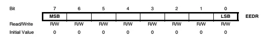
- EEPROM Data Register (EEDR)
- EEPROM Control Register (EECR)
- PortA Input Pins
- PortB Input Pins
- Write Button connected to PD6
- Read Button connected to PD7
- PortC Output for Bar Graph LED
The Atmega32 microcontroller consists of two primary memory spaces: the Data Memory and the Program Memory, along with an additional EEPROM Memory designated for data storage. This EEPROM Memory is non-volatile, contributing to the controller’s three distinct memory spaces, all of which exhibit linear and regular properties.
The EEPROM memory space stores a maximum of 1024 bytes of data, separated from the data space. It allows for single-byte reading and writing operations and endures approximately 100,000 write/erase cycles. The access time for this space is approximately 8.5ms when using the internal RC clock set at 1MHz.
Even when the device enters the power-down sleep mode, the EEPROM write operation persists. However, it’s important to note that the device is not entirely powered down during this phase. Therefore, it’s advisable for the programmer to verify the EEPROM before transitioning the device into a complete power-down mode.
Instances of EEPROM corruption can arise due to insufficient supply voltage leading to erroneous instruction execution. To mitigate this, enabling the internal Brown-out Detector (BOD) can be effective. If the BOD fails to address the issue, an additional VCC reset protection circuit can be added as a preventive measure.
In Assembly language, low-level programming necessitates the direct use of I/O and Peripheral Registers. However, when employing C programming for the AVR, these registers remain concealed from the programmer.
Before accessing the EEPROM memory, specific registers need to be utilized.
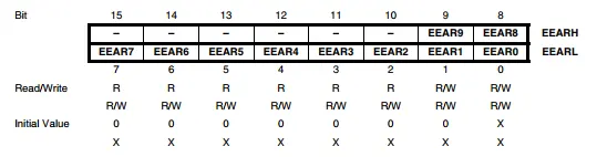
The address register consists of a 16-bit pair, but only 10 bits are utilized, resulting in a 10-bit (1024) address space. This configuration allows users to access a maximum of 1024 bytes within the EEPROM memory.

This memory comprises:
Bits 7 to 4 – Reserved Bits
Bit 3 – EERIE: EEPROM Ready Interrupt Enable
Bit 2 – EEMWE: EEPROM Master Write Enable
Bit 1 – EEWE: EEPROM Write Enable
Bit 0 – EERE: EEPROM Read Enable
For AVR Lib-C on an AVR device, managing these registers isn’t necessary. Programmers can utilize the eeprom.h library, accessing the EEPROM memory through its read and write functions.
However, in this programming instance, we’ll utilize all these registers. The provided example will demonstrate a straightforward approach to accessing the internal EEPROM.

The controller will read and write the internal EEPROM data. The data will display on PortC.
-
/*
-
* m32Eeprom.c
-
*
-
* Created: 7/20/2022 6:43:00 PM
-
* Author : desktop
-
*/
-
#include <avr/io.h>
-
/*Write button connects to PD6*/
-
#define writeButton ((PIND&0x40)==0)
-
/*Read button connects to PD7*/
-
#define readButton ((PIND&0x80)==0)
-
/*EEPROM Write Function*/
-
void eepromWrite(unsigned int addr,unsigned char dat){
-
/*Wait for completion of previous write*/
-
while(EECR&(1<<EEWE));
-
/*Set up address and data registers*/
-
EEAR=addr;
-
EEDR=dat;
-
/*Write logical 1 to EEMWE*/
-
EECR|=(1<<EEMWE);
-
/*Start eeprom write by setting EEWE*/
-
EECR|=(1<<EEWE);
-
}
-
/*EEPROM Read Function*/
-
unsigned char eepromRead(unsigned int addr){
-
/*Wait for completion of previous write*/
-
while(EECR&(1<<EEWE));
-
/*Set up address register*/
-
EEAR=addr;
-
/*Start eeprom read by writing EERE*/
-
EECR|=(1<<EERE);
-
/*Return data from data register*/
-
return EEDR;
-
}
-
int main(void)
-
{
-
/*PORTC Output*/
-
DDRC=0xFF;
-
/*PA0…PA3 Input*/
-
DDRA=0xF0;
-
/*PORTB Input*/
-
DDRB=0x00;
-
/*Turn on porta and portb high*/
-
PORTA=0x0F;
-
PORTB=0xFF;
-
/*Turn on PD6 and PD7*/
-
PORTD=(1<<6)|(1<<7);
-
while(1)
-
{
-
/*eeprom read task*/
-
if(readButton)
-
{
-
/*Wait until the button released*/
-
while(readButton);
-
PORTC=eepromRead(PINA);
-
}
-
/*eeprom write task*/
-
if(writeButton)
-
{
-
/*Wait until the button released*/
-
while(writeButton);
-
eepromWrite(PINA,PINB);
-
}
-
}
-
}
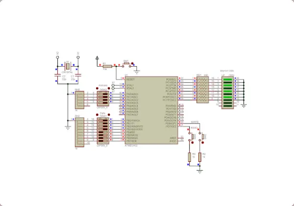
PortA functions as the input for addresses. Specifically, we utilize four bits capable of accommodating up to 16 addresses. PortB, on the other hand, serves as the input for data used in internal EEPROM writing. The write button is linked to the PD6 pin, while the read button connects to the PD7 pin. Furthermore, PortC is interfaced with a bar graph LED to visually display the data retrieved from the internal EEPROM.
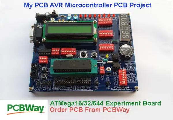
Should you require a conventional PCB designed for the ATMega32 micro-controller, you have the option to purchase my AVR Microcontroller project through PCBWay at an affordable rate. Click this link to obtain a complimentary $5 credit for new accounts.
- How many bytes can the EEPROM memory store?
The EEPROM stores a maximum of 1024 bytes of data. - Can the device enter complete power-down mode during EEPROM write?
No, the device is not entirely powered down during this phase. - What causes EEPROM corruption and how can it be mitigated?
Insufficient supply voltage causes corruption; enabling the internal Brown-out Detector helps mitigate this. - Which bits are utilized in the 16-bit address register pair?
Only 10 bits are utilized out of the 16-bit pair. - What function does Bit 0 in the EEPROM Control Register serve?
Bit 0 is labeled EERE and serves as the EEPROM Read Enable. - How does C programming differ from Assembly regarding registers?
In C programming, I/O and Peripheral Registers remain concealed from the programmer. - What components are used to input addresses in the example project?
PortA functions as the input for addresses using four bits. - Where is the retrieved data displayed in the simulation?
The data retrieved from the internal EEPROM displays on PortC. - How many write/erase cycles can the EEPROM endure?
The EEPROM endures approximately 100,000 write/erase cycles.