Summary of Mini Oscilloscope
This article details the construction of a portable, battery-powered mini oscilloscope using an STM32F030F4 microcontroller. The author prioritized speed and cost-efficiency by utilizing Direct Memory Access (DMA) for data transfer and a 1.8-inch TFT display. The device features a 1V/div sensitivity, measures voltages between -6V and +6V via a virtual ground offset, and includes a rotary encoder for controls. While not matching high-end digital scopes, it effectively handles audio and low-frequency experiments up to 50kHz.
Parts used in the Mini Oscilloscope:
- Plastic box (12 x 8 x 3 cm)
- Perfboard (double sided prototype board 8x12cm)
- STM32F030F4 microcontroller
- TSSOP20 to DIP board
- ST7735s 1.8 inch TFT display
- Lithium-ion battery
- HT7333 3.3V low dropout regulator
- MCP6021 opamp
- 8 MHz crystal
- Rotary encoder plus knob
- Powerswitch
- Banana terminals
- Lithium-ion charger board
- Resistors and capacitors
- Nylon spaces, nuts and screws
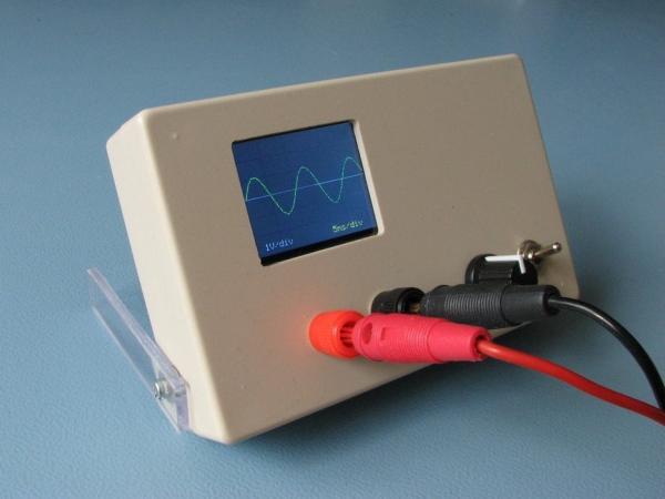
This is an Instructable about a mini oscilloscope I made, it isn’t anywhere near as capable as a real (digital) oscilloscope (such as my Rigol) but I think it is nice to have. Even more important, I enjoy making things, even when they have no real use. For an example of that, just look at my “tuning fork oscillator”.
Browsing the internet I came across some simple diy oscilloscopes, usually made with an Arduino or Arduino compatible board but almost always with the Arduino software. The trouble with these is that an Arduino isn’t very fast, its ADC isn’t either and the Arduino software certainly isn’t known for its speed. So some people added a separate ADC to it, which increases the hardware complexity and the total price.
I thought it could be done easier and cheaper and still have a reasonable performance. And I’m a fan of the STM32 series of ARM microcontrollers made bij ST Microelectronics so I picked one of those. I also like to do a project with the smallest, and often cheapest, microcontroller possible but still with acceptable performance.
EDIT: Code is now available on GitLab
https://gitlab.com/WilkoL/mini-oscilloscope
Step 1: Microcontroller: STM32F030F4
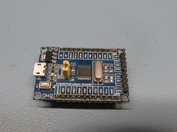
development board. Inside this microcontroller there is a decent ADC, it can do a conversion in 1us. The results of the conversions can be read from a register but, and that is very important here, also transfered via DMA to any place in memory making the process very fast and without loading the cpu. In this microcontroller there are the usual timers, it has SPI and I2C, a RTC, a USART and 2 Watchdogs. Of course you cannot use all peripherals at the same time as this version of the STM32F030 has just 20 pins and some of those are used for things as power, reset, crystal, programming and boot-selection. To program the microcontrollers made by ST Microelectronics you need a tool called the STLink-V2, available via Mouser, Farnell and others, a cheap clone of it is available on Ebay and others. The STM32F030F4 board is sold for less the 3 euro and the STLink-V2 for a similar price. If you have an official development board made by ST Microelectronics themselves such as a “Nucleo-board” there is a STLink-V2 on it that can be snapped off of it. That’s what I did and I put it in a small plastic box.
Step 2: Part List
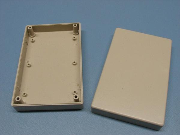
- plastic box (12 x 8 x 3 cm)
- perfboard (double sided prototype board 8x12cm)
- STM32F030F4
- TSSOP20 to DIP board
- ST7735s 1.8 inch TFT display
- lithium-ion battery
- HT7333 3.3V low dropout regulator
- MCP6021 opamp
- 8 MHz crystal
- rotary encoder plus knob
- powerswitch
- banana terminals
- lithium-ion charger board
- several resistors and capacitors, nylon spaces, nuts and screws
Step 3: Tools Software and Documents
Tools
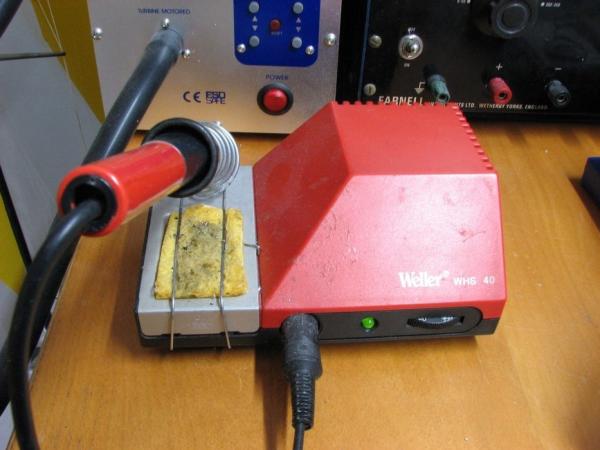
soldering station
solder 0.7mm
solder wick
flux
some wire
side cutter
glasses and loupe
drill
multimeter
oscilloscope ( 🙂 )
STLink-V2
coffee
Software
STM32IDE (integrated development environment)
STM32CubeMX
STLink Utility
LowLayer library (not the HAL !)
library for ST7735s TFT (ported to STM32)
Notepad++
Kicad (for schematic only)
Spotify (for background music)
Documents
STM32F030 datasheet
STM32f030 reference manual (RM0360)
Step 4: Preparation
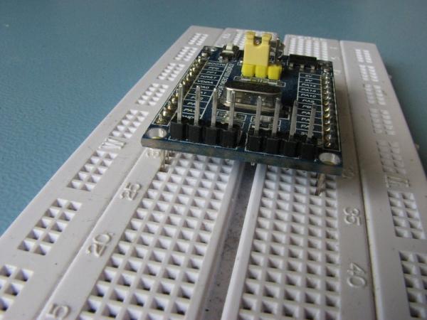
As usual I start all projects on a breadboard. Unfortunately the STM32F030F4 development board is too wide to be used on a single breadboard. And it is too narrow to be used on two breadboards connected together! The solution to this is to remove one of the power rails from a breadboard, then it fits like a charm. (see picture)
But as I tried to fit all the parts in the plastic box I found that the STM32F030F4 board was a bit too big. So on the pcb I went for a bare chip and therefore I had to add the other components such as decoupling capacitors, crystal, low dropout voltage regulator myself. A TSSOP20 chip is way too small for me to use as it is, so I soldered it on a TSSOP20 to DIP board. It isn’t very easy to do but with patience, a steady hand glasses and a loupe it is possible. I have done it several times with TSSOP20 and LQFP48 chips without real problems. You will also need flux and (in my case) solder wick to remove any shorts.
BTW, I don’t intent to design a PCB for this project as I will make just one of it.
Step 5: Specifications
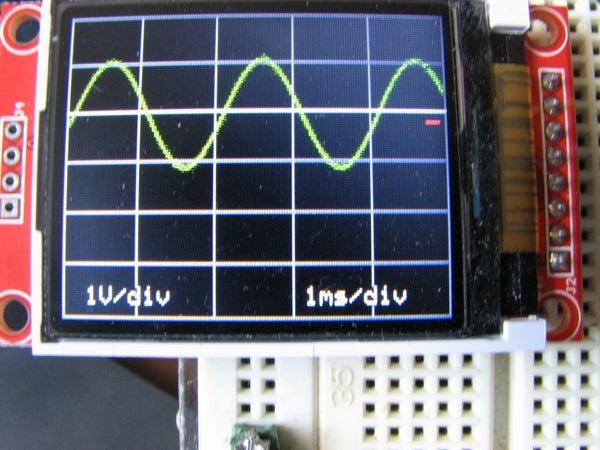
The TFT screen has a resolution of 160 x 128 pixels, that means that the X-axis (timebase) needs 160 ADC samples. The ADC needs a minimum of 1 us per sample and I think that 10 waves of a signal of such a small screen is at the limit of what is useful. This means 16 pixels per waveform. As the ADC needs about 1us per sample that’s 16us, that’s a waveform with a frequency of 62500 Hz. That’s not much when you are used to a real 100 MHz digital oscilloscope, but it is enough for audio, led-projects, and more low frequency experiments.
In the end I could not even get the ADC do 1.000.000 conversions per second so I settled for 800.000. The time-base therefore goes up to 40us/division. With 5 divisions on the screen it means 200us per full screen. A 5 kHz waveform then fills the whole screen and I think the limit of usefulness is around 50kHz. On the lower end I decided that 200ms/division (1 second/screen) was a nice time, so then a 1Hz signal uses the entire width of the screen.
The ADC converts the voltage on its input referenced to 3.3V (Vdd). You can choose the resolutions 12, 10, 8 and 6 bits and the lower you go, the faster the conversions are. As the TFT screen has an Y-axis (vertical resolution) of 128 pixels (7 bits) it isn’t needed to have the ADC do better than 7 bits, but a 7 bit resolution isn’t available, so it is set to 8 bits. The least significant bit will be discarded by a shift-right of 1 bit.
Attenuation is required to be able to measure a bit more than 3.3V the ADC is capable of, amplification if you want to measure smaller signals than that, and it would be nice to be able to measure a negative voltage too. This means either to have a positive and negative powersupply or to have an offset added to the input voltage. Because I wanted to use just one battery and keep the device as simple as possible, the offset-method was chosen. This means that the ground-terminal of the input is not connected to ground at all, it is connected to the offset voltage, this I call the virtual ground. It also means that you have to use this oscilloscope battery powered.
The oscilloscope has just one sensitivity: 1 Volt / division. I did think of adding an amplifier and an attentuator with small relais or a digital potentiometer. But the relais I have need at least 5V to work and the digital potentiometer was too noisy to be useful. Of course you can add an amplifier and/or attenuator to it, just put it in front of the input. Next, the oscilloscope shouldn’t put a big load on the circuit you are measuring. Most oscilloscopes use 1 Mohm, and so does this one. You can use a real 10x probe with it, that will increase both the voltage range and input impedance tenfold, but you may also have to add frequency compensation with a variable capacitor. I haven’t tried it.
The analog bandwidth of an oscilloscope needs to be a high as possible, as a rule of thumb, at least 10 times the frequency you want to measure. After all, a squarewave of just 10 kHz has many harmonics and you need to have at least 90 kHz bandwidth to see the ninth harmonic. Said another way, if you try to see a squarewave of 10MHz on a 10 MHz oscilloscope you will see very little squarewave but mostly a sinewave of 10 MHz. Here a bandwidth of 500kHz would be enough, but more is better. I used an opamp with a gain/bandwidth product of 10MHz a Microchip MCP6021, for the simple reason that I have some in stock. If you want to use another, remember it needs to work at 3.3V.
With an offset from 0V to 3V the acceptable voltage on the input goes from -6V to +6V. But always with a maximum top-top value of 6V! So either from -6V to 0V via -3V to +3V up until 0V to + 6V. Good enough for most Arduino project you may have, and if needed, doubling the input resistor from 1Mohm to 2Mohm will also double the voltage range.
The trigger level can be set anywhere on the screen, that means that it can be set from almost -6V to almost +6V. But it actually has nothing to do with any voltages at all, only with the position of the trace on the screen. It also only acts on the rising edges of a signal. If you want you can add the option to trigger on a falling edges as well, add it to the source, I didn’t think it was necessary.
The last specification I want is that the Lithium Ion battery can be charged via a small board with a mini-usb connector. At first I wanted to use a 18650 size lithium ion battery but it was too big, now a small rectangular battery is used, it has the same dimensions as a (dumb)phone battery Samsung and others used in their phones but it i twice as thick. Just use any lithium ion battery you have and that fits. As long as the nominal voltage is 3.7 volt it is fine.
In short these are the specs
- input resistance
- 1Mohm sensitivity
- 1V/div timebase 200ms/div…40us/div
- input voltage -6V…+6V
- trigger level any level on screen
- battery powered
Step 6: Hardware and Schematic
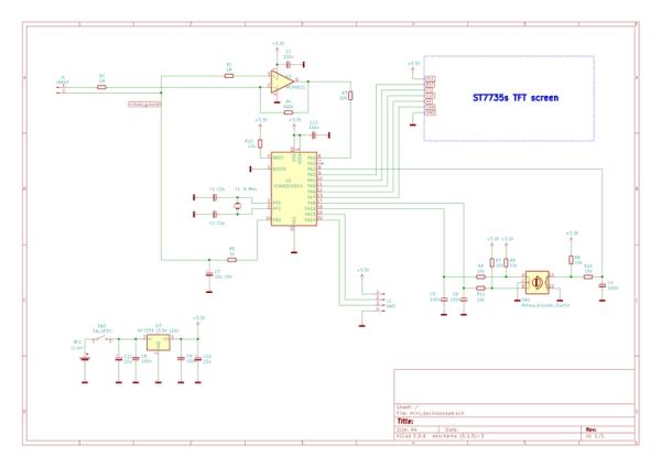
Well, just look at the schematic, it is pretty simple. If you use a STM32F030F4 on the development board there is very little to do besides the connections to the display, rotary encoder and the opamp. Even the voltage regulator is on the board!
I did not use the development board because I was afraid it wouldn’t fit in the plastic box. I use the microcontroller soldered on the TSSOP20 to DIP board. Because this DIP board sits rather high above the PCB I can place many parts, such as the crystal and some capacitors, under it. And the lithium ion battery fits nicely under the display 🙂
Step 7: Inner Workings
TFT-library
First of all I needed to get the display working. Fortunately for most standard displays there are ready-to-use libraries, but I couldn’t find one for this display and a STM32 microcontroller. The one I ported to STM32 was made for Arduino (made by Sparkfun? Adafruit? Someone else?). I don’t remember and I didn’t keep the original source or the name(s) of the original makers when I ported it to STM32, sorry about that.
– So all the honours for the ST7735 library go to the makers, whoever they are –
After porting it to STM32 I found that the display isn’t very fast. Luckily it uses SPI and you can make SPI go rather fast on this microcontroller. But still I needed to send the least possible data to it to keep the refresh rate of the display reasonable. I haven’t measured it but I think, at the shortest timebase setting it is around 15 to 20 Hz. On the longest timebase setting (200ms/div – 1 second/screen) you will notice that the refresh rate isn’t 1 Hz, but just 0.5 Hz! I’ll explain that later.
The really, really bad Rotary Encoders Second, the rotary encoder needs to be read. This caused most problems for me, not that I didn’t know how to do this, it is just a simple quadrature signal. No, it turned out that all 10 of the encoders I bought (Ebay) were of such poor quality that I needed not only to do software debouncing but also debouncing in hardware. And still I cannot turn the knob all too fast as it will miss pulses. Normally I do software debouncing only, as it doesn’t need anything extra, no pullup resistors, no capacitors, but in this case they were very much needed.
ADC and DMA The most important thing is getting analog data in. As I said, the ADC does an 8 bit conversion in about 1us. It is started by a timer (TIM3) that runs continuously and sends pulses to the ADC according to the curent timebase setting. The lowest rate (200ms/div –> 1 second/screen) is 160 Hz. So the ADC does 160 conversions per second, filling the 160 pixel screen in 1 second. The highest rate is 800 kHz, so the screen is filled in 160*(1/800.000) = 200us. If only the display and software were that fast! Then you could have a refresh rate of 5 kHz. (any old analog scope does that without breaking sweat)
Instead the data from the ADC is transfered to an array: adc_buffer[] in memory. This is done with DMA, witch means that the cpu of the microcontroller is not needed to do that, it can continue with whatever it is doing. This makes storing the data very simple and fast. When the DMA is ready with the programmed number of values it needs to transport, it sets the TC-flag (transmission complete) and triggers an interrupt. The interrupt itself doesn’t do much, it just clears the TC-flag and sets a variable called “token” as a signal to the main routine telling it that there is data ready to be displayed. The ADC continues conversions and the DMA keeps transporting those results to the adc_buffer[]. So no matter what else there is going on inside the microcontroller, there is a never ending stream of values coming into adc_buffer[].
Triggering As said, the display is 160 pixels wide so only 160 values are needed to show a complete waveform. The adc_buffer[] actually contains 320 samples. So the DMA stores 320 values in it before it triggers a TC interrupt. This is done because the triggering is done in software. And as it is very unlikely that the first value in the adc_buffer[] is the place where the triggering should be. We have to find the place where that point is. So 320 values are read and in the first 160 of these the actual trigger point is searched.
What is done is that in the adc_buffer[] the trigger point is found by checking if the value is at the trigger value en if the next value is just above it. This works quite well, but you need a bigger buffer than the actual display size is. I tried with double the size and quadruple the size, but that made very little difference, so I stuck to 320.
This too is the reason that the refresh rate on the lower timebase settings is slower than you might expect. As I mentioned before when you use the 200ms/div setting, one screen full of data takes 1 second, but because double the amount of conversions is done, it takes 2 seconds. On the faster timebase settings you will not notice it that much.
Source: Mini Oscilloscope
- Why did the author choose the STM32F030 over an Arduino?
The author chose the STM32 because Arduinos are too slow with poor ADC performance, whereas the STM32 offers fast conversion speeds and DMA support. - How is the input voltage range handled without a negative power supply?
An offset method is used where the ground terminal connects to a virtual ground voltage, allowing measurements from -6V to +6V. - What is the maximum useful frequency this oscilloscope can measure?
The limit of usefulness is around 50kHz, though the timebase supports frequencies up to 5kHz filling the whole screen. - How does the device manage data storage without loading the CPU?
Direct Memory Access (DMA) transfers ADC results directly to memory, allowing the CPU to remain free for other tasks. - What resolution is set for the ADC and why?
The ADC is set to 8 bits because the screen has 128 pixels (7 bits), making higher resolution unnecessary and slower. - Why was hardware debouncing required for the rotary encoder?
The specific encoders purchased were of poor quality, requiring both software and hardware debouncing to function correctly. - Can this device be powered by a standard mains adapter?
No, the device must be battery powered because the input ground is connected to a virtual ground offset rather than earth ground. - What is the input impedance of this oscilloscope?
The oscilloscope has an input resistance of 1 Mohm.