Summary of Morse code interpreter, with speech synthesis Using Atmega32
This project implements a bidirectional Morse Code system: it decodes audio Morse (5–40 WPM, benchmark 20 WPM) to text and speech, and encodes typed text to Morse audio. Hardware includes a Schmidt Trigger to digitize a 750 Hz tone, an ATmega32 MCU for sampling and state-machine decoding/encoding, a Parallel R-2R DAC for clean sine output, and dataflash-stored compressed speech for text-to-speech via an SPO256-AL2. Modes include audio-input decoding with speech output and HyperTerm text entry with Morse audio output. Standards used: RS-232, SPI, and International Morse Code.
Parts used in the Morse Code Interpreter Project:
- STK-500 Development Board
- AT45D021A-RC Dataflash
- 6 inch Solder Board
- Power Supply for STK-500
- Black and White TV
- 2-pin Flat Jumper Cables
- DIP Sockets
- Headphone Jack and Speaker
- Piezo Speaker
- Resistors and Resistor Packs (assorted)
- Capacitors (assorted)
- Op-amps (LM358N)
Introduction
This project implements a system that translates Morse Code to text and speech and translates text to Morse Code.
With our limited experience with Morse Code, our first task was to do some research on the components of Morse Code and the standards associated with it. After we familiarized ourselves with Morse Code, our second task was to understand the waveform generated by Morse Code. On the American Radio Relay League website, we found some sample wave files of various words-per-minute (WPM), ranging from 5 to 40 WPM. Prior to their dropping of the requirement of amateur radio enthusiasts to operate below the 30 MHz range, the FCC administered the test at 20 WPM. We decided that this would be our benchmark. On another website, we found a wave file that contained the alphabet played at 20 WPM. This helped us tremendously throughout the project in debugging our sampling code and circuitry.

To implement our Morse Code system, we had to use both hardware and software. Since the Morse Code audio was that of a 750 Hz sine wave, we had to build a Schmidt Trigger to digitize the signal before sampling it. In our code, we used two state machines–one to detect the dots, dashes and spaces and another to determine the characters associated with the dots and dashes. To output the Morse Code, we used the Parallel D/A Direct Digital Synthesis (DDS) scheme presented on Professor Land’s website. To accomplish text-to-speech, we encoded the 100 most commonly used words in English (in addition to a few extras and a silence) and stored the compressed audio in dataflash. The audio is decompressed on the fly when the word is found in the table; otherwise, the system outputs a beep. All of these parts were essential for achieving our goal.
System Overview
[ rationale ][ background ][ logical structure ][ hardware/software tradeoffs ][ standards ][ patents ]
Rationale
This idea was perpetuated on the fact that we had secured a text-to-speech IC (an obsolete SPO256-AL2 chip, we later discovered). We brainstormed for various applications of speech synthesis, and finally decided on a Morse Code project. Morse Code is used today by amateur radio enthusiasts and also by disabled people–specifically mute–to communicate with others. The latter of these uses is what inspired us to pursue our project. People with severe motor disabilities are able to communicate in Morse, either by blowing and sucking into air tubes or by blinking their eyes. We thought that a system that would be able to translate the Morse Code to text and to speech as well as translate the text to Morse Code would be extremely useful for people with disabled family members and/or friends. With this system, they would still be able to “speak” with their loved ones.
Background
Morse Code was developed in the early 1840s by Samuel F. B. Morse to enable long-distance communication using an electronic telegraph. At the time, the technology was not capable of printing legible characters; hence, Morse Code was used instead. Throughout the first half of the 20th Century, Morse Code served as the dominant form of high-speed communication; however, with the advent of telephones and the internet, its current uses are limited. It mainly serves as an assistive technology and as a means for amateur radio operators to get on the airwaves, which is the most popular use today. Up until 2003, the International Telecommunication Union (ITU) mandated Morse Code proficiency in order to obtain an amateur radio license, but since then more and more countries have dropped this requirement. There are six components of Morse Code: dots, dashes, inter-character gaps, short gaps, medium gaps and long gaps. The following definitions are adapted from Wikipedia:
- dot: short mark
- dash: long mark
- inter-character gap: space between dots and dashes for a character
- short gap: space between letters
- medium gap: space between words
- long gap: space between sentences (we did not use this one)
Unfortunately, we were not able to find a standard for the duration of each. Wikipedia provides a relationship between the different components, but when we actually measured the durations of the different components on the Tektronix TDS 210 oscilloscope, we found that the relationships varied by WPM, and none of them matched up with the one proposed on Wikipedia. Table 1 shows the durations of the components for the 7 WPMs that we incorporated into our system.
Mode 1
In this mode, we give the MCU a Morse message (10, 15, 20, 25, 30, 35 or 40 WPM) that is played from the computer through a headphone jack that has been stripped (great scavenging find!!). We use a Schmidt Trigger to convert it to a series of HIGHs and LOWs. Our system then decodes the message and outputs the text to HyperTerm. It also checks to see if any of the text is one of the prerecorded words (in our case, one of the 100 Most Common English Words) stored in dataflash (through SpeechWord) and outputs that to the speaker on the TV. If not, then the sound will be a small beep indicating unfound word.
Mode 2
In this mode , the user can type into HyperTerm, and the MCU will encode the message in into Morse Code audio using a DAC system. This will be fed to a small piezo speaker for output.
Hardware/Software Tradeoffs
- To generate the sine waves for Morse Code output, we decided to use a Parallel D/A instead of the PWM. This required us to store the sine wave in flash memory and build the R-2R DAC, but the end result was a much cleaner signal.
- We used 2-Mbit dataflash to store the compressed speech. This required us to use the SPI protocol and introduced timing issues (that resulted from reading from the flash) to our real-time system, but after all the kinks were worked out, we had a library of more words than if we had not used dataflash.
Standards
In this project, we used the RS-232 standard to communicate with Hyperterm on the computer via serial, the SPI protocol to write and read from the dataflash, as well as the definitions of International Morse Code. Using the exact definitions allows us to make this a system useable by other people as opposed to being just a demonstration.
Patents
There are no patents or copyrights associated with this project.
Program/Hardware Design
Morse Code Processing
The first stage of processing the Morse Code is putting the signal through a Schmidt Trigger. A Schmidt Trigger operates like a comparator circuit with positive feedback. By choosing the values of the feedback resistors, we were able to preset the threshold at which the Schmidt Trigger triggers. The threshold value of the Schmidt trigger is determined by the following formula, ±(R1/R2)*Vs. By using a 20K resistor for R1 and a 1M resistor for R2, we achieved a threshold value of -100 mV since our Vs value was the 5V from the STK-500 (refer to Figure 1 for our circuit). There was some percentage of error associated with our threshold value due to the 5% accuracy of the resistors we used. Our Schmidt Trigger normally outputs HIGH, which is determined by the op-amp (3.75V); however, when the input signal falls below -100 mV, the output switches to LOW until the signal goes back above -100 mV, at which point it will switch back to outputting HIGH
The result of using the Schmidt Trigger is that we obtained a 57% duty cycle square wave (600us LOW, 800us HIGH) whenever a 750 Hz sine wave (representing Morse Code audio) was present at the input terminal (see Figure 2). The output from the Schmidt Trigger was connected to PORTA.0 on the MCU so that the Mega32’s internal ADC could be used to decode the waveform. We set the ADC to run at a speed of 2MHz (by setting the prescalar to 011) so that it would be fast enough to accurately read the waveform.
We only know that audio is present on the input whenever the Schmidt Trigger output goes LOW; however, since it is only in this state for a brief 600us for every period, choosing the right sampling frequency was crucial for attaining an accurate detection system. Originally, we decided to sample the waveform at 5kHz so that when we sampled two consecutive LOW values (this provided more accuracy than if we had just determined the value based on one sample), then we would know that we had a signal. Since this required the Timer ISR to run every 200us, we decided on an alternate method–to detect falling and rising edges. This allowed us to run the Timer ISR at 2kHz so that we could sample the waveform every 500us. The duration for which the signal is LOW is 600us; thus, we ensure that we will detect it at least once by sampling every 500us. If we had sampled every 600us, we would have risked missing the LOW peaks altogether. Every time a sample is taken, a flag, blipready, is asserted so that the “blip detection” state machine could be run.
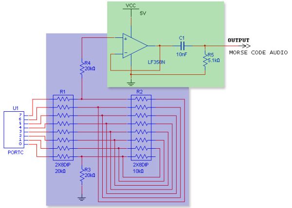
Figure 3 depicts the state machine embedded in the detect_blip() function that was used to decipher a dot from a dash and a short gap from a long one. The state machine is initialized to the “done” state, where it waits for the A/D input, Ain, to be 0, indicating that there is a signal. When this condition is met, the state machine transitions to the “noblip” state. In this state, if the current Ain is less than the previous Ain, prevAin (that is set to the current Ain at the end of the function), then the blipcount variable is incremented; otherwise, the state machine transitions to the “yesspace” state and increments spacecount. The purpose of the using the less-than operator is that if the current input is less than the previous input, then we know that a falling edge has been encountered. On the other hand if the current input is greater than or equal to the previous one, then we know that it is either staying steady or a rising edge has been encountered. The state machine stays in the “yesspace” state until another falling edge is encountered, at which point it transitions back to the “noblip” state.
Parts List:
| Component | Cost/Item | Quantity | Cost |
|---|---|---|---|
| STK-500 Development Board | $15.00 | 1 | $15.00 |
| AT45D021A-RC Dataflash | Free (already on STK-500) | 1 | 0.00 |
| 6″ Solder Board | $2.50 | 1 | 2.50 |
| Power Supply for STK-500 | $5.00 | 1 | 5.00 |
| B/W TV | $5.00 | 1 | 5.00 |
| 2-pin Flat Jumper Cables | Free (courtesy of the lab) | 9 | 0.00 |
| DIP Sockets | $0.50 | 3 | 1.50 |
| Headphone Jack & Speaker | Free (salvaged) | 1 | 0.00 |
| Piezo Speaker | $1.00 | 1 | 1.00 |
| Resistors & Resistor Packs (Assorted) | Free (courtesy of the lab) | 7 | 0.00 |
| Capacitors (Assorted) | Free (courtesy of the lab) | 3 | 0.00 |
| Op-amps (LM358N) | Free (courtesy of the lab) | 3 | 0.00 |
| Total | $30.00 | ||
For more detail: Morse code interpreter, with speech synthesis Using Atmega32
- What does the project do?
It translates Morse Code audio to text and speech, and translates typed text to Morse Code audio. - How is the Morse audio digitized?
A Schmidt Trigger converts the 750 Hz sine wave audio into a digital HIGH/LOW square wave for the MCU to sample. - What MCU is used for processing?
An ATmega32 microcontroller is used for sampling, decoding, encoding, and interfacing. - How is speech synthesized?
Compressed audio for the 100 most common English words is stored in dataflash and decompressed on the fly for playback via the speech IC; unknown words produce a beep. - How is Morse output audio generated?
A Parallel R-2R DAC using a stored sine table (Parallel D/A DDS) generates the Morse Code audio played on a piezo speaker. - What communication standards are used?
RS-232 for HyperTerm serial communication, SPI for dataflash access, and International Morse Code definitions. - What sampling strategy detects dots and dashes?
The Schmidt Trigger output is sampled every 500 microseconds via a Timer ISR, and a state machine detects falling/rising edges to classify blips and spaces. - Why use a Parallel D/A instead of PWM?
Parallel D/A produced a much cleaner sine wave output despite requiring flash storage and an R-2R ladder.