Summary of Mushroom Climate Box
This article details the construction of a modular climate box for growing mushrooms, featuring ESP32-based temperature and humidity control. The system utilizes a Peltier element for heating and cooling, an ultrasonic nebulizer for fog generation, and BME280 sensors for monitoring. The project emphasizes modularity, allowing users to reproduce individual components like the thermal engine and fog generator independently.
Parts used in the Mushroom Climate Box:
- ESP32 Microcontroller
- Breadboard
- Socket
- Box for switch cabinet
- Styroporbox
- 2x BME280 temperature and humidity sensor
- Cable ties
- Pins
- 6x 1m cable
- 1x jumper
- 2x breadboard 4x3 holes
- 2x male triple Dupont connector
- 2x female triple Dupont connector
- Container for water (airtight)
- Ultrasonic nebuliser with power supply unit
- 12V fan
- 1m tube
- 3x tube adapter
- 3x T-piece for tubes
- 2x relay
- Peltier element
- Passive cooling fin
- Active cooling fin
- 4 relay module
- Approx. 2m cable
- 8 conductor end caps
- Resistor
- Jumper cable
- 12V power supply
- 150x150 plate
Hi there!
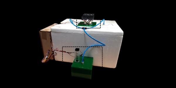
i have built a climate box to grow mushrooms. It can regulate both temperature and humidity. The heating or cooling works with a peltier element. The air humidity is increased with an ultrasonic nebuliser. I have built everything modular, so that you can also reproduce individual parts.
Have fun with the manual
Step 1: Bill of Materials
General
– ESP32 – Microcontroller
– Breadboard
– Socket
– Box for switch cabinet
– Styroporbox
Climate measurement
– 2x BME280 temperature and humidity sensor
– cable ties (fixing)
– pins (fixing)
– 6x 1m cable
– 1x jumper
-2x breadboard 4×3 holes
– 2x male triple Dupont connector
– 2x female triple Dupont connector
Fog generator
-Container for water (airtight)
– Ultrasonic nebuliser with power supply unit
– 12V fan
– 1m tube
– 3x tube adapter
– 3x T-piece for tubes
– 2x relay
Thermal Engine
– Peltier element
– passive cooling fin
– active cooling fin
– 4 relay module
– approx. 2m cable
– 8 conductor end caps
– resistor
– jumper cable
– cable approx. 1m to control the fan
– 12V power supply
– 150×150 plate
Step 2: Box and Sensors
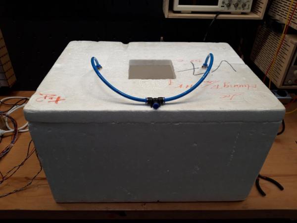
First of all you have to prepare the styrofoam box. To do this, cut a rectangular hole for the thermal machine in the lid with a cutter knife. You also need to cut two small round holes in the lid for the hoses. You can use a soldering iron for this. In the box itself you can also cut a hole for the sensor cables.
After all the holes are cut in the box, plug the pneumatic hoses together. Then push them through the two round holes in the lid. They should sit firmly in the holes and not wobble.
Now you can mount the sensors. I have soldered them on a grid of holes and fixed them with a cable about one meter long. Under this link you can find instructions how to connect BME280 sensors.
https://randomnerdtutorials.com/esp32-web-server-w…
Note that if you are using two sensors, it is necessary to change the I2C address on one of the sensors. You do this by connecting SDO to VCC on one of the two sensors.
Now attach the sensors to the walls of the box and lead the cable out. Furthermore I have installed a small 12V fan to circulate the air in the box. Pin needles are very suitable for fixing the sensors.
Step 3: Thermal Engine
The thermal engine is the key component to change the box-temperature. The engine is powered by a peltier-element. By switching the polarity (12V) you can either heat or cool. This is done by four relais which are controlled by an esp32 microcontroller (works quite similar like an arduino).
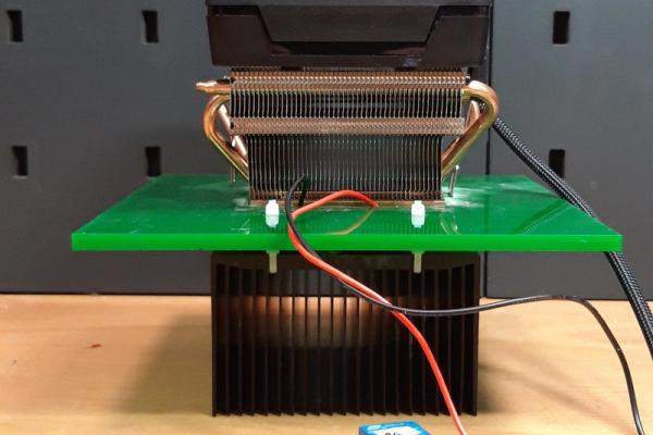
For the assembly you need two headsinks, a fan, a flat plate and some cable ties.
First you have to cut a hole in the plate with the size of the Peltier element. In my case this was 40x40mm. When you choose the plate, you should make sure that it has the same thickness as the Peltier element. Next, I drilled four more small holes in the plate, to which the lower cooling fin is attached. For this I recommend cable ties, because they conduct heat badly in contrast to screws. After the lower cooling fin is fastened to the plate, you can glue the Peltier element to the cooling fin with some heat-conducting paste. Make sure that the cables of the Peltier element are led out cleanly. Now glue the cooling fin with integrated fan onto the Peltier element with a little heat-conducting paste.
Now only the wiring of the components is missing. To connect the Peltier element correctly, you have to split the two cables of the Peltier element into two cables each. This works simply by soldering two more cables to each of the cables of the Peltier element. You now plug each of the four cable ends into one of the relays of the relay board. The circuit diagram shows this once again. To connect the fan, simply connect according to the overall wiring diagram.
You may wonder why four relays are used. With the help of the relays it is possible to turn the voltage of the Peltier element around. So, depending on the switching of the relays, it can heat or cool.
Step 4: Fog Generator
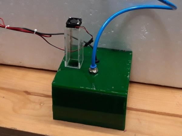
Next we build the fog generator. For this you cut 3 holes in the waterproof container. A big one for the fan to blow air through and two small ones for the pneumatic hose and the cable of the fan. I recommend to build a small base for the fan. This prevents water from splashing on the fan. The ultrasonic nebuliser is then placed in the container and the cable is led through one of the holes. The connection for the pneumatic hose is placed in the last hole. If you cut a thread in the hole, you can easily fix it.
Both the fan and the ultrasonic nebuliser must be connected to a relay. For the fan you do this by using jumper cables. For the ultrasonic nebuliser you have to strip the cable. Then you put on one of the phase wire end caps and plug it into the relay. The other phase can simply be soldered back together and insulated with some heat shrink tubing.
The construction of the fog generator was based on instructables manuals. Here is an example:
https://www.instructables.com/id/Water-Only-Fog-Ma…
To operate the nebuliser, you now have to fill water into the container and off you go. Tip: Use distilled water, this will increase the lifetime of the ultrasonic nebuliser.
Step 5: Final Assembly
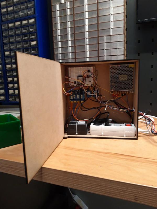
Now all components (styrofoam box, thermal engine, fog generator) are assembled and then wired. The assembly is actually quite simple. You put the lid on the box. Then you put the thermal engine into the square cut of the lid. Then connect the fog generator with the blue pneumatic hoses to the connections on the lid. Now all that is missing is the wiring of all electrical components. Therefore I have built a small switch box made of wood in which I fix all parts. For wiring the relays and sensors with the ESP32 I use a pinboard.
The schematic shows how you wire everything. Actually you only have to connect the relays to the digital outputs of the ESP32. Furthermore the relays need 5V voltage and a connection to ground. Also the sensors have to be connected. Another digital output is needed for the big fan on the Peltier element. Finally, all fans and actuators must be connected to the 12V power source. The only exception is the ultrasonic nebuliser, because it needs 24V.
Attention: Please find a specialist if you want to connect the power source to 230V yourself and are not familiar with it.
Step 6: Code
The last thing you have to do is load the code onto the ESP32. You can use the software Arduino IDE or Visual studio code for example. Here you can find instructions on how to set up the ESP32 in the Arduino IDE:
https://randomnerdtutorials.com/installing-the-esp…
Just connect the ESP32 to your computer with a micro usb cable and load the code onto it. You can find the code in the attached file. In the code, you can make some changes, for example:
– set the target values
– set tolerance for the control
Step 7: Troubleshoot
In this last step you will find problems that might occure while crafting the box. I will keep updating the troubleshoot.
Source: Mushroom Climate Box
- How do I change the I2C address on one of the two BME280 sensors?
You must connect SDO to VCC on one of the two sensors. - What material is recommended for fixing the lower cooling fin to the plate?
Cable ties are recommended because they conduct heat badly in contrast to screws. - Why are four relays used in the thermal engine assembly?
Four relays allow you to turn the voltage of the Peltier element around so it can either heat or cool. - What type of water should be used to increase the lifetime of the ultrasonic nebuliser?
Distilled water should be used to increase the lifetime of the ultrasonic nebuliser. - Does the ultrasonic nebuliser require the same voltage as the other fans?
No, the ultrasonic nebuliser needs 24V while all other fans and actuators connect to the 12V power source. - Can I build this project if I am not familiar with connecting power sources to 230V?
No, you should find a specialist if you want to connect the power source to 230V yourself. - What software can be used to load the code onto the ESP32?
You can use the Arduino IDE or Visual Studio Code to load the code onto the ESP32. - What happens if I solder screws instead of using cable ties for the cooling fin?
Screws conduct heat better than cable ties, which is why the author recommends cable ties to avoid unwanted heat conduction.