
Summary of Pacemaker Challenge on AVR/Butterfly Boards
This article details a model-based development framework for prototyping safety-critical embedded systems, using AVR/Butterfly boards, a heart simulator, and pacemaker controller logic. It covers formal modeling, verification, automatic code generation, and hardware validation, emphasizing real-time timing, resource constraints, and extensions like DDD mode, hysteresis, and rate smoothing. Implementation specifics include AVR platform features, development tools (AVR Studio, WinAVR), bf_gcc sample usage, port I/O, RTC vs busy-wait timing, LCD and joystick handling, and sound generation for alerts.
Parts used in the Pacemaker Challenge on AVR/Butterfly Boards:
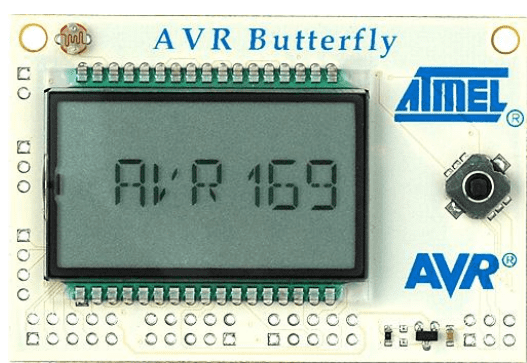
- AVR Butterfly board (ATmega169 MCU)
- AVR/Butterfly LCD display
- Light sensor (onboard)
- Temperature sensor (onboard)
- 4 Mbit DataFlash (onboard)
- Buttons and joystick (onboard)
- Speaker (onboard)
- Standard header pins for I/O
- RS-232 interface (optional)
- Heart simulator (software model or separate AVR board)
- Pacemaker controller software module (running on AVR)
The design and development of safety-critical embedded systems demand a rigorous methodology that ensures reliability, timing accuracy, and correct functionality under all conditions. This article presents an in-depth commentary and technical walkthrough of a model-based development framework centered around the use of AVR/Butterfly boards, heart simulators, and pacemaker controller systems. We explore the theoretical modeling, software implementation, and hardware interfacing necessary for prototyping safety-critical systems such as artificial pacemakers. With a combination of model-driven design, formal validation, real-time control, and embedded programming practices, this project serves as a valuable case study for medical-grade embedded applications.
Introduction: Model-Based Development for Critical Systems
In domains such as medical electronics, aviation, and automotive control systems, safety is paramount. Any software controlling these systems must be verifiable and deterministic. To meet these goals, this project employs model-based development (MBD) as its central methodology. MBD enables the creation of formal models that can be verified for correctness, safety properties, and functional validity before deployment on hardware.
The key phases in this workflow include:
-
Formal model creation using simulation tools and specifications,
-
Verification of properties through formal methods and simulations,
-
Automatic code generation from the model, ensuring fidelity,
-
Validation via real hardware tests, particularly on AVR/Butterfly microcontroller boards.
Embedded Development Concerns and Timing Constraints
When working with safety-critical embedded systems, two primary concerns dominate:
-
Real-time responsiveness, especially under deterministic constraints, such as a pacemaker reacting within milliseconds to heartbeats.
-
Resource-constrained hardware, which necessitates careful programming to avoid timing delays, memory overflows, or signal misreads.
These concerns are amplified in biomedical applications, where precise, repeatable timing is not just a matter of performance, but of life and death.
Implementation Architecture
The architecture of the system involves a combination of simulation models and physical hardware:
-
Heart Simulator: A model that either generates random heartbeats or responds to pacing signals.
-
Pacemaker Controller: An embedded control logic that triggers pacing if the heart doesn’t beat on its own.
-
AVR/Butterfly Board: The hardware platform that interfaces both simulation and control units.
-
Signal Communication: Achieved by reading/writing port values between AVR boards representing the heart and the controller.
Four core components are orchestrated:
-
VPace and APace: Represent ventricular and atrial pacing.
-
VBeat and ABeat: Represent detected beats.
Signals are transmitted via GPIO ports on the AVR/Butterfly boards, simulating real electrical communication between the pacemaker and the heart.
The Heart Simulator: Behavior and Extensions
The Heart Simulator mimics two essential behaviors:
-
Autonomous Beating: Random timing between 100ms and 1900ms simulates natural heart rhythm.
-
Resettable Timer: When externally paced, the simulator resets its internal clock to simulate a biological response to artificial stimulation.
To enhance realism, extensions include simulating both ventricular and atrial chambers. This duality allows the system to represent complex timing relationships in DDD pacemaker modes.
The Pacemaker Controller
At the core of the system is a software module responsible for:
-
Monitoring beat signals from the heart simulator,
-
Initiating pacing if a heartbeat is not detected within a prescribed interval.
Extensions provide advanced features such as:
-
DDD Mode: Dual-chamber pacing and sensing.
-
Hysteresis: Allowing the heart to beat slightly slower before pacing.
-
Rate Smoothing: Preventing abrupt changes in pacing intervals.
This mimics modern pacemaker algorithms and encourages students or developers to explore real-world challenges in biomedical engineering.
The AVR/Butterfly Board Platform
The AVR Butterfly board serves as the hardware backbone of the project. Key features include:
-
ATmega169 MCU: Low-power microcontroller with embedded peripherals.
-
LCD Display: For real-time feedback and monitoring.
-
Sensors: Light and temperature sensors offer opportunities for adaptive responses.
-
4Mbit DataFlash: Used for data logging.
-
Buttons and Joystick: For manual input during testing or simulation.
-
Speaker: Allows for audio alerts or simulations of pulse signals.
Access to standard header pins and RS-232 further extends the board’s connectivity for additional testing or communication.
Development Environment Setup
Programming and debugging the system requires:
-
AVR Studio 4.18 with Service Pack 1: Provides an intuitive IDE for writing and flashing code.
-
WinAVR: A GCC-based toolchain that allows embedded C programming for the AVR platform.
The correct installation sequence is crucial: install AVR Studio first, followed by WinAVR to ensure toolchain integration.
Using the bf_gcc Sample Program
To expedite development, the project employs the bf_gcc sample code, which is a GCC-compatible version of the AVR Butterfly demo. This codebase includes usage examples for:
-
LCD output,
-
Button inputs,
-
Power-saving modes,
-
Sleep behavior.
Available at Siwawi AVR Projects, this resource provides a foundational codebase for modification.
System Logic and Behavior
The main program logic follows this pattern:
-
Initialization: PowerSave, clocks, state pointers, etc.
-
Main Loop:
-
Display current state on LCD.
-
Capture button input.
-
Transition to new states if needed.
-
Enable AutoPowerSave or SleepMode if idle.
-
Use AutoPress logic to account for short button holds.
-
This system enables responsive interaction with minimal power consumption—an essential feature in battery-powered embedded devices like pacemakers.
Hardware Interfacing and Feature Implementation
Joystick Handling
Button inputs are captured via getkey() and mapped to:
-
KEY_ENTER,KEY_NEXT,KEY_PREV,KEY_PLUS,KEY_MINUS.
LCD Control
Functions such as:
-
LCD_puts()– displays string, -
LCD_UpdateRequired()– signals LCD refresh, -
LCD_Clear()– clears screen content, -
LCD_Colon()– toggles colon display.
These abstractions enable rapid interface development.
Port I/O
AVR ports are manipulated in two steps:
-
Direction Configuration:
-
Example:
DDRB = 0xF0sets upper bits as output.
-
-
Data Handling:
-
Read:
PINB, Write:PORTB.
-
Similar logic applies to PORTD, keeping in mind that not all pins are accessible due to board layout.
Real-Time Clock and Software Delays
Two methods are employed for timekeeping:
-
RTC with Interrupts:
-
Accurate and efficient; used for periodic tasks.
-
-
Busy Waiting with Delays:
-
Less precise; uses
util/delay.hfor small delays.
-
Clocks are also used to time music playback, by linking audio functions to timer interrupts.
Generating and Playing Sounds
Sound generation is performed by:
-
Defining frequency, tempo, and duration,
-
Sending waveform signals to the speaker via OC1A pin,
-
Registering sound functions to timer interrupts to synchronize tones.
This mimics auditory alerts that would be useful in medical alarms or alerts in real pacemakers.
Conclusion
This project exemplifies the synergy between model-driven software design and embedded hardware control in the context of safety-critical applications. The AVR/Butterfly board, with its accessible interface and powerful features, enables rapid prototyping of complex control systems like artificial pacemakers. By modeling, verifying, and validating software before deployment, engineers can ensure safety and correctness—a necessity in the medical field. The extensions in pacing logic, user interaction, and signal handling make this a rich project for both academic research and hands-on embedded systems education.
Source: Pacemaker Challenge on AVR/Butterfly Boards
- What is the central development methodology used in the project?
Model-based development (MBD) with formal modeling, verification, code generation, and hardware validation. - Can the AVR Butterfly board simulate both heart and pacemaker functions?
Yes; signals are transmitted via GPIO ports between AVR boards to represent heart and controller communication. - How does the Heart Simulator model natural heartbeats?
By generating autonomous beats with random timing between 100 ms and 1900 ms and resetting its timer when externally paced. - What pacemaker features are implemented or extended in the project?
Features include DDD mode, hysteresis, and rate smoothing. - What development tools are required for programming the AVR Butterfly?
AVR Studio 4.18 with Service Pack 1 and WinAVR (GCC-based toolchain). - How are port I/O and pin directions configured on the AVR?
By setting direction registers such as DDRx (example DDRB = 0xF0) and reading/writing PINx and PORTx registers. - What timing methods are used for real-time tasks?
RTC with interrupts for accuracy and busy waiting with util/delay.h for small delays. - How is user input handled on the AVR Butterfly?
Using getkey() to map buttons to KEY_ENTER, KEY_NEXT, KEY_PREV, KEY_PLUS, and KEY_MINUS. - Can the system produce audio alerts and how?
Yes; by defining frequency, tempo, and duration and sending waveform signals to the speaker via the OC1A pin using timer interrupts.
