Summary of Printed Circuit Board for Introductory Animatronics Course
This article details the modernization of a Computer Engineering course at Cal Poly, transitioning from Arduino-based animatronics to standalone breadboard prototyping and custom PCB design using Fritzing software. The project aims to equip freshmen with hands-on electronics manufacturing skills, including microcontroller programming, servo noise reduction, and circuit fabrication. Key deliverables include step-by-step instructions, Fritzing tutorials, bills of materials, and finalized PCB schematics for an animated stuffed animal project.
Parts used in the Animatronics Controller Project:
- ATmega328p microcontroller
- Breadboard
- Servo motors
- Barrel jack power module
- Oscillator circuit components
- Fritzing prototyping software
- Custom motor shield (original setup)
- LEDs and capacitors
- Resistors
- Power supply components
Introduction
For many years, freshmen Computer Engineering students at California Polytechnic State University have taken a course introducing electronics manufacturing processes. Lectures cover CAD/CAM design, Design for Manufacture, documentation, prototyping and planning. The lab allows students to build skills in project planning, soldering, automation, tool usage and production methods by manufacturing their own power supply from raw materials and an unassembled PCB.
While popular, faculty see the need for modernization to keep pace with emerging tools. Arduino and Fritzing now enable non-degree holders to easily learn microcontroller programming and PCB design. With this in mind, Dr. Smith is testing an optional elective course with potential to fill this role. Previously, students built and programmed animated stuffed animals using Arduino and a custom motor shield.
In collaboration with Dr. Smith, we have expanded the course by adding individual PCB design for each student. The Arduino/shield setup can now be replaced with a standalone breadboard prototype. These updates leverage modern programming and prototyping methods to impart hands-on skills beyond traditional degree requirements. The enhanced course prepares students for innovation using accessible technologies outside a formal curriculum.
My role involved exploring approaches to transitioning the project from an Arduino setup to a standalone breadboard prototype and student-designed printed circuit board (PCB). This required compiling hardware specifications for operating an ATmega328p microcontroller independently of the Arduino. Additionally, I produced breadboard and PCB reference designs utilizing Fritzing’s prototyping software interface.
Building upon my reference models, I generated a set of step-by-step directions guiding students through the process. Starting with components and a breadboard, the instructions take students from crafting an initial breadboard prototype to culminating in a custom PCB design. My contributions aimed to enable migrating the coursework to leverage modern development methods while retaining hands-on practical experience for participants.
Stakeholders
This project falls under the guidance of Dr. Hugh Smith of California Polytechnic State University’s Computer Engineering department. As instructor for the experimental CPE 200 “animated stuffed animal” course, Dr. Smith aims to augment it with PCB design elements as outlined.
Funding derives from HuSmith, Inc., a private software consultancy located in San Luis Obispo, CA. Additional stakeholders include CPSU’s Computer Engineering and Industrial/Manufacturing Engineering departments (CPE and IME).
CPE and IME seek to leverage this course as an alternative for introducing freshmen to electronics manufacturing concepts via IME 156. Meanwhile, computer engineering students would benefit from a fun, hands-on project covering PCB design and manufacturing skills integral to a well-rounded education in their field.
By enriching the curriculum in these impactful ways, the project serves to advance learning for both departments and their joint student populations. Guidance from Dr. Smith and support from HuSmith facilitate these educational endeavors.
Client Needs and Discussion
Through discussions with Dr. Smith, I understood the animatronics course’s underlying goal and scope of the PCB project. My role was to develop the PCB portion for CPE students according to the requirements below:
Create step-by-step breadboard prototype instructions
Complete a microcontroller PCB design
Document known issues and common design pitfalls for future iterations
Develop Fritzing tutorial materials for breadboarding and PCB design
Research and implement servo noise reduction methods
The CPE Department and Dr. Smith envisioned a fun, cost-effective way for students to experience electronics manufacturing and build skills crucial for computer engineering careers. Focusing on robotics and firmware programming offers more relevance compared to assembling a power supply.
Providing hands-on robotics and PCB practice through this project aims to impart rewarding and practical experiences that enrich learning outcomes for CPE students and the department at large. My task involved crafting educational materials and deliverables meeting this objective.
Goals and Objectives
The overarching aim of this project expands on an existing animatronics course by incorporating breadboard prototyping and PCB design/assembly into the curriculum.
Specific goals and objectives include:
Develop step-by-step instructions guiding students through breadboard prototyping of a microcontroller circuit for an animatronic device.
Design a printed circuit board layout that implements the microcontroller system in a portable, robust format for students to assemble.
Create educational materials teaching the Fritzing prototyping software environment to model breadboard prototypes and design PCB schematics.
Research and document techniques for mitigating servo motor noise in prototypes and PCB designs.
Produce deliverables that enrich the course material and expose students to practical skills in electronics manufacturing through hands-on robotics and circuit design projects.
The intended outcome is a more well-rounded educational experience imparting in-demand abilities rooted in relevant technologies.
Goals
Craft a set of lab assignments for students in the CPE 200 course.
Create lecture content and curriculum materials to instruct students in completing an animated stuffed animal project.
Design and implement a breadboard prototype incorporating additional components like servos and a power module.
Evaluate the viability ofminiaturizing the design onto a printed circuit board.
Develop a reference PCB schematic and layout.
Shepherd students through the project hands-on, ensuring they gain meaningful insights.
The goal is to modernize the course content by incorporating contemporary prototyping methods andcircuits design practice through an engaging hands-on learning experience. Objectives focus on curriculum development, prototyping, evaluation of design integration, and student guidance.
Objectives
Research external power solutions for integrating servos with the PCB-based design.
Create initial Fritzing wiring diagrams for the standalone breadboard controller prototype.
Compile a bills of materials listing required components.
Construct the breadboard prototype and validate correct functionality.
Develop step-by-step instructions guiding students to build the breadboard controller.
Evaluate feasibility and transition approaches for migrating the design to a printed circuit board.
Design an animatronics controller PCB schematic using Fritzing.
Procure a test run of the manufactured PCB design and verify its operation with an animated skeleton model.
Testing and validation of the PCB controller.
The focus is on research, prototyping, documentation, design, fabrication, and verification tasks necessary to evolve the project’s implementation using contemporary methods.
Outcomes and Deliverables
Project deliverables will comprise a set of step-by-step instructions, breadboard schematics, a printed circuit board layout, and a fully functional animatronics controller.
These materials lay the groundwork for guiding students in future iterations of the course. Specifically, the written documentation (provided in appendices) contains:
Breadboard prototype wiring diagrams
Bills of materials for required components
Tutorial for the Fritzing prototyping software
Breadboard assembly guide for students
PCB schematic design
Gerber files for fabrication
Assembly and usage guide for the PCB controller
Together, these deliverables modernize the course content through incorporation of contemporary prototyping and circuit design techniques. They serve to impart practical skills while establishing a foundation to further enrich engineering education.
Breadboard Fritzing Steps and Files:
Fifteen Fritzing breadboard diagrams depict an iterative process of constructing a standalone animatronics controller prototype on breadboard. Each step adds discrete subsystems like the barrel jack power module or oscillator circuit. Photorealistic views illustrate the evolving breadboard system.
While the .fzz design files themselves are omitted from appendices for brevity, they have been provided to Dr. Smith. Accompanying them is a .fzbz parts bin file containing components needed for student breadboards. Using these predefined parts ensures accurate pinouts and PCB footprints that match purchased components.
Collectively, the schematic snapshots and curated parts library establish a reference design workflow guiding students incrementally from an empty breadboard through fully integrating discrete circuit elements into a functional prototype controller.
Breadboard Instructions:
A document lays out the parallel processes of gathering parts and constructing both the physical breadboard prototype as well as its corresponding Fritzing schematic representation. Instructions cover importing the course-specific parts bin file, wiring configurations for the controller and its constituent subsystems, and basic operational descriptions of key components.
To aid comprehension, screenshots illustrate the Fritzing interface and component photos clarify what students should procure. Upon following these coordinated guidelines, learners can concurrently build and diagrammatically model the developing prototype controller. Together, the hands-on building and virtual modeling reinforce comprehension of circuit design principles.
Printed Circuit Board (PCB) Final Design File:
The “.fzz” Fritzing design file labeled “Step 15” contains an updated, refinement PCB design incorporating lessons learned throughout researching circuit porting approaches onto a printed circuit board. Photographs in appendices visually compare both PCB revisions relative to discovered design factors.
Collectively, these iterations document evolving the controller schematic from breadboard prototype to a finalized printed circuit layout ready for fabrication. Students benefit from tracing how adjustments addressed challenges surfaced through evaluating the transition from experimental prototyping to a permanent solution.
PCB-Related Instructions:
Several documents provide guidance for transitioning the animatronics controller design onto a printed circuit board.
The design considerations document supplies information needed to maintain functionality of the ATmega328p microcontroller on a standalone PCB.
Instructions are also included for testing board connections prior to assembly to verify electrical accuracy.
Additionally, a reference sheet outlines notes and reminders for students as they solder components to populate their manufactured PCBs.
Collectively, these resources establish requirements, validation procedures, and assembly guidelines for implementing the controller circuit on printed circuitry integrated in a compact form factor suited for instructor and student use when fulfilling course objectives related to PCB development.
Fritzing ‘Getting Started’ PowerPoint Presentation:
A brief presentation introduces students to Fritzing’s breadboarding and schematic views. It guides learners through a foundational tutorial exercising basic functions. Specifically, students will draw a simple two-LED circuit powered through an Arduino breadboard prototype within Fritzing.
By modeling this rudimentary design, students can become familiar with depicting a breadboard layout as well as generating a neat schematic representation. The goal is to expose participants to Fritzing’s interface for constructing virtual breadboard and circuit diagram renditions – core skills when developing more advanced projects on the platform.
Bill of Materials:
This document comprises a bill of materials listing the components required for the PCB, along with their quantities and estimated costs.
It also includes the pricing details for the printed circuit boards procured for the specific needs of the course offered in Spring 2015.
By outlining the parts, costs, and actual PCB expenses, this resource ensures students have transparency into the projected budget when replicating the controller design on their own populated printed circuit boards for the class project. It establishes realistic financial expectations.
Background
This project explored three key areas relevant to reproducing an Arduino/shield project on a standalone printed circuit board (PCB).
The first area examined was the Fritzing prototyping environment. Fritzing is an open-source software tool developed by Friends-of-Fritzing and IXDS to support the design of electronic prototypes, schematics, and PCBs. It allows users to develop breadboard prototypes, layout circuit diagrams, and design PCB schematics. This tool was covered in my CPE 200 course in Spring 2015.
The second area investigated was the feasibility of recreating the Arduino/shield project entirely on a custom PCB rather than using a development board and shield.
The third area researched was techniques for mitigating noise on servos connected to a PCB. Excessive noise can interfere with precise servo movement.
Details on the findings from exploring each of these three topics are provided below to provide relevant background information for this project.
Parts Pane
The Fritzing software contains a Parts pane which houses all the component libraries included with the program, such as parts from vendors like Sparkfun, Arduino and Analog Devices. As shown in Figure 1, this pane allows access to all available components.
Within Fritzing, each individual electronic part is referred to as a “part”. A part contains a photorealistic image of the component for the breadboard view, a symbol used in schematic diagrams, and one or more physical layouts for printed circuit boards. The Parts pane enables users to create custom component libraries, build their own parts bins, and import third-party libraries of additional parts. This gives designers flexibility in the parts they can incorporate into their Fritzing projects.
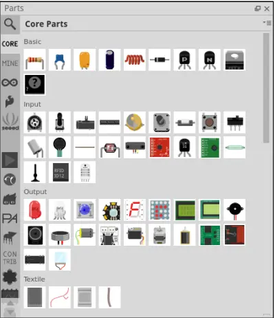
Many common electronic components in Fritzing, such as LEDs and capacitors, have multiple variants with differing printed circuit board (PCB) layout implementations. To ensure students selecting parts would choose designs compatible with PCB fabrication, I customized a CPE 200 Fritzing component library. This library contained only the appropriate PCB package options for each component. I then distributed this library to students for their projects. Component characteristics like PCB layouts can be modified using the Parts Inspector tool. By standardizing on a curated list of PCB-ready parts, I aimed to facilitate students’ successful transition from schematic design to manufactured circuit boards.
Parts Inspector Pane
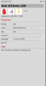
As shown in Figure 2, the Parts Inspector allows users to modify the properties and characteristics of Fritzing components. Attributes that can be adjusted include nominal values (e.g. resistance levels for resistors, capacitance for capacitors), voltage ratings, package types, colors, and other specifications. Some property settings, such as resistance values, serve documentation purposes only since Fritzing does not incorporate circuit simulation capabilities. While it does not validate circuit function, the Parts Inspector gives designers control over component properties for reference and consistency across different component variants and views within a Fritzing project.
Breadboard Prototype Design:
The Breadboard View, depicted in Figure 3, enables users to design breadboard prototypes within Fritzing by adding and interconnecting electronic components. Designers can freely place parts and route wires between them, modeling a project setup. When doing so, the software automatically tracks the circuit connections behind the scenes. These mappings are then recognized in the Schematic and PCB views to maintain consistency across representations. Within the Breadboard View, wires can be colored and routed with bend points as needed to easily distinguish and follow important connections. This feature allows users to visually organize complex breadboard designs for both documentation and fabrication purposes.

We utilized Fritzing’s breadboard modeling capability by having students first physically assemble their circuit prototypes on an actual breadboard. They were then instructed to use their physical breadboard as a visual guide to recreate the exact same wiring configuration within Fritzing’s Breadboard View. This process allowed them to leverage the realism of Fritzing’s photorealistic breadboard representation while ensuring their on-screen design accurately corresponded to their physical prototype.
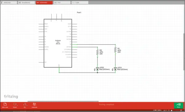
Schematic View:
As shown in Figure 4, Fritzing features a Schematic View which provides circuit symbol drawings and pinout diagrams for every part compatible with the software. When components and connections are added and defined in the Breadboard View, Fritzing automatically generates a corresponding schematic representation. Similar to specialized PCB design programs, Fritzing utilizes “ratsnest” routing to visually connect each electrical node in the circuit with dotted lines. While the Schematic View itself does not enable functional testing or verification, it serves as an excellent documentation and communication tool by allowing users to create clean, professional-grade system diagrams. This helps designers evaluate and explain their designs outside of the context of a breadboard prototype.
Printed Circuit Board (PCB) View:
A primary focus of this project was evaluating Fritzing’s printed circuit board (PCB) design capabilities. While Fritzing may not offer all the advanced features of specialized PCB design software, it provides an excellent introduction to basic PCB concepts for beginners. Its intuitive interface and straightforward workflow make it perfectly suitable for an introductory course like CPE 200 animatronics. In Fritzing’s PCB View, users can define a custom board outline by importing an SVG file and create up to two signal layers for routing traces. Common PCB design tools like design rule checking, auto-routing, copper pours, ground pours (where copper fills are automatically tied to ground), and extended Gerber file generation are supported. For this iteration of the course, students were instructed to rely primarily on Fritzing’s auto-router rather than perform extensive manual routing. Figure 5 below depicts a sample completed student PCB design within Fritzing. My reference schematic designs used for both course revisions are included in the Appendix for reference.
Source: Printed Circuit Board for Introductory Animatronics Course
- How can students transition from an Arduino setup to a standalone prototype?
Students replace the Arduino/shield setup with a standalone breadboard prototype and then migrate the design to a custom printed circuit board. - What software is used for designing the breadboard prototypes and PCBs?
The Fritzing prototyping software interface is used to model breadboard prototypes and design PCB schematics. - Why was a custom Fritzing component library created for the course?
A custom library was created to ensure all parts had appropriate PCB package options compatible with fabrication, preventing students from choosing incompatible designs. - How does the course address servo motor noise issues?
The project includes research and documentation on techniques for mitigating servo motor noise in both prototypes and PCB designs. - What are the primary deliverables provided to students?
Deliverables include step-by-step instructions, breadboard wiring diagrams, a bill of materials, Fritzing tutorials, PCB schematics, Gerber files, and assembly guides. - Can students use the auto-router feature in Fritzing for their PCB designs?
Yes, students were instructed to rely primarily on Fritzing's auto-router rather than performing extensive manual routing. - How do students verify electrical accuracy before assembling the PCB?
Instructions are provided for testing board connections prior to assembly to verify electrical accuracy. - What is the role of the Parts Inspector tool in Fritzing?
The Parts Inspector allows users to modify properties like nominal values, voltage ratings, and package types for consistency across component variants.