Summary of Programming AVR Microcontrollers with Atmel Studio 7
This article shows how to program an ATTiny2313 AVR microcontroller using Atmel Studio 7 and an ISP programmer. It covers downloading/installing Atmel Studio, writing a simple C program to blink an LED on PB4, wiring a 6-pin ISP connector (VTG, GND, MOSI, MISO, SCK, RST), building and uploading the firmware, and troubleshooting common connection issues.
Parts used in the Programming AVR Microcontrollers with Atmel Studio 7:
- Windows 10 computer
- ATTiny2313 microcontroller (or other AVR microcontroller)
- Atmel/Microchip AVRISP mkII or similar ISP programmer
- USB cable for ISP programmer
- Custom circuit board with LED connected to PB4
- 6-pin ISP connector and wiring (VTG, GND, MOSI, MISO, SCK, RST)
- Atmel Studio 7 software
- Anti-malware software (recommended)
- Anti-static workstation (recommended)
Inexpensive microcontrollers have seen a resurgence thanks to the internet of things (IoT) and wearable devices. These end-uses depend on parts that have low costs rather than record-breaking speed. Because of this, devices like the Atmel AVR series have enjoyed decades of popularity.
Any software we develop for these devices eventually needs to go from being an abstract idea, to being software stored inside the device’s flash memory. This walkthrough will do exactly that using a program called Atmel Studio 7.
Notice of Non-Affiliation and Disclaimer: As of the publication date, we are not affiliated with, associated with, authorized with, endorsed by, compensated by, or in any way officially connected with Microchip Technology Inc., Arduino, or Microsoft, or their owners, subsidiaries or affiliates.
The names Microchip Technology Inc., Arduino, and Microsoft, as well as related names, marks, emblems, and images are trademarks of their respective owners.
External Links: Links to external web pages have been provided as a convenience and for informational purposes only. Unboxing Tomorrow and Voxidyne Media bear no responsibility for the accuracy, legality or content of the external site or for that of subsequent links. Contact the external site for answers to questions regarding its content.
Objectives
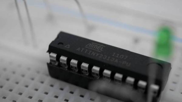
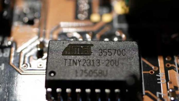
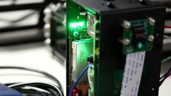
The circuit board in Figure 1 below is the custom part of a machine vision side-project going on here at Unboxing Tomorrow. On the circuit board is an ATTiny2313-20SU microcontroller. As part of the AVR family, the ATTiny2313 is a low-cost, 8-bit microcontroller unit (MCU) made by the Atmel Corporation and its parent company: Microchip Technology.
Because the chip arrives in a blank state, we need to download the Atmel Studio 7 application to a laptop, and then write a program in C to blink a test LED on the circuit board. Additionally, we will use a hardware programming device to perform In-System Programming (ISP) on the chip.
For now, today’s objectives are simple:
- Download Atmel Studio 7
- Write a C program to blink a test LED on the custom circuit board
- Use the ISP Programmer to upload the C program from a laptop to the actual chip
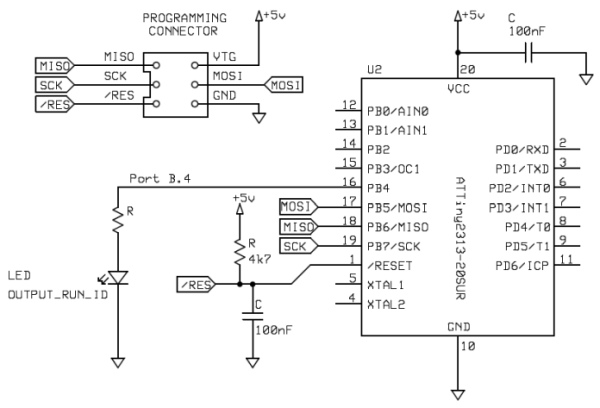
This schematic below is a simplified version of the custom circuit board. Our code will be uploaded through a 6-pin ISP connector, where it will eventually blink an LED attached to port B pin 4 (PB4).
Material Requirements
As usual, I recommend doing any assembly work at an anti-static workstation if you can.
- Windows 10 Computer
- ATTiny2313 (or other AVR microcontroller)
- Microchip/Atmel AVRISP mkII or similar ISP programmer with matching USB cable
ISP Programmer Device
This tutorial will focus on the Atmel/Microchip AVRISP mkII (also called AVRISP “mark 2”). But I should note that this is an older device that is difficult to find as of the year 2020. But you can find newer ISP devices from Microchip that work very much like the AVRISP mkII.
Software Requirements
We will also be installing a program from Microchip called Atmel Studio 7. While there is other software available for programming AVR microcontrollers, Atmel Studio 7 is the official integrated development environment (IDE).
- (We will install) Atmel Studio 7
- (Recommended) Anti-malware software
Back up your Data
You should back up any important data on your laptop or desktop before you start.
The Microcontroller will be Erased
This procedure will erase and replace any programs or bootloaders already stored on your Atmel AVR microcontroller. Replacing these things is a difficult process.
- Do not perform the procedure below if your Atmel microcontroller is part of a development kit such as an Arduino. If you do, you will erase the bootloader and your kit will not work.
If you bought your Atmel microcontroller from a distributor, it is probably already blank and you should be okay to proceed.
Downloading Atmel Studio
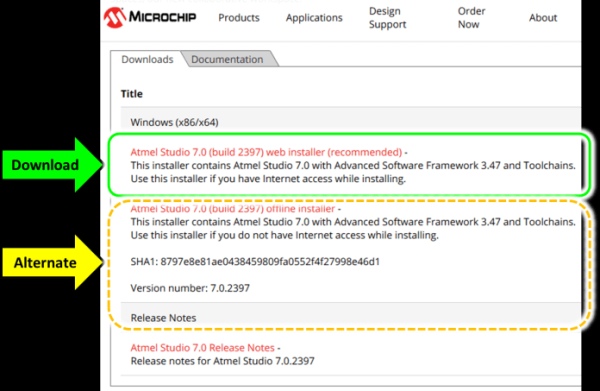
The first step is to visit Microchip Technology’s official website for the Atmel Studio 7 IDE. As of this writing, the direct link is https://www.microchip.com/mplab/avr-support/atmel-studio-7.
I will download the web installer from the official website…
As with anything you download off the internet, scan it with your favorite anti-malware software. If it looks okay, run the application.

Prior to installation, you should review the end-user license agreement and the installation directory. After you have reviewed them, click Next.
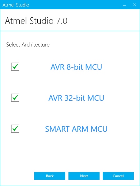
Next, you will be asked to select among the following architectures:
- AVR 8-bit MCU
- AVR 32-bit MCU
- SMART ARM MCU
This article only depends on the AVR 8-bit MCU, so at minimum, you should count on installing AVR 8-bit MCU. But I will install all three today…
Next, you will be asked about the Atmel Software Framework (ASF) and example projects. In this tutorial, the ASF is optional, but I will install it anyway.

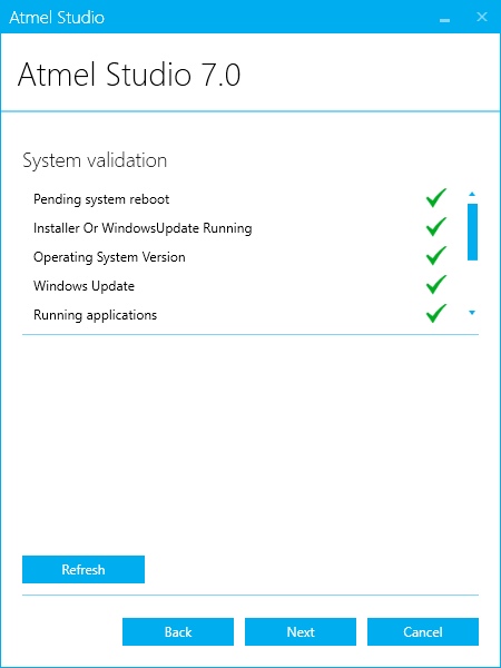
Before it attempts to install anything, the installer will check for anything that may interfere. This includes any Windows Updates already in progress. If you see anything other than checkmarks, you will need to resolve the problem before you can proceed. Follow any on-screen instructions on how to do this.
If things look okay, click Next.
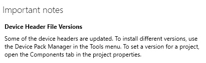
Next, the installer will show any special tips that may help your installation.
Click Next, and the installation will begin. Acknowledge any security alerts from Windows unless they look suspicious.
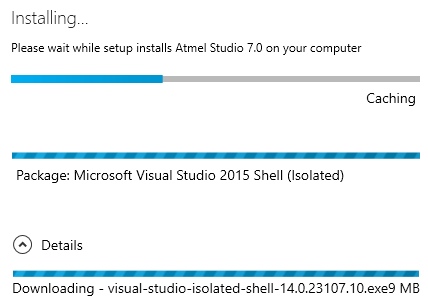
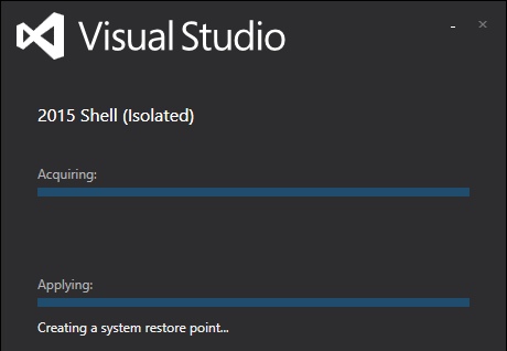
The system will automatically transition from installing Atmel Studio to installing the Microsoft Visual Studio isolated shell. But stick around to monitor it in case you are asked to approve anything.
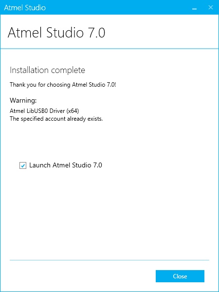
After several minutes, the installation should complete. Make sure “Launch Atmel Studio 7.0” is checked (

) so you can start it immediately.
Building a C Program
Now that Atmel Studio 7 is installed, launch it.
Create a New Project
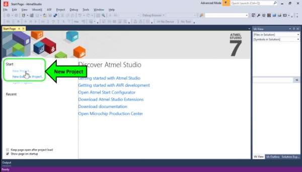
First, create a new project by clicking the New Project label on the Start Page. If the start page isn’t visible, you can instead navigate to File –> New Project.
Next, it is time to select the programming language. This project will use the C coding language, so select GNU Compiler Collection C (GCC C). Select C/C++ in the top-left corner first. Then select “GCC C Executable Project.”
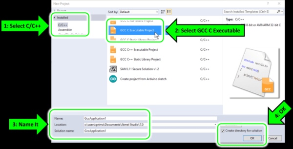
Before you click “OK,” you may want to rename your project or change the location. Today, I will accept the default name of “GccApplication1.”
I also recommend making sure “Create directory for solution” is checked (). When you are ready, click “OK.”
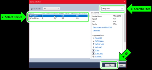
Next, you will be asked to select your specific Atmel device. It’s a long list, so you may want to use the search filter on the top-right corner to enter a portion of the device part number.
I am using the ATtiny2313, so that’s what I will select.
Coding Main.c
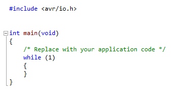
Atmel Studio 7 will populate the editor field with a very basic main() function…
Now would be a good time to review the simplified schematic…
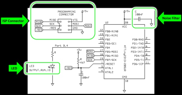
Only 3 things matter for now:
- Compiling a test program to blink the LED (named OUTPUT_RUN_ID)
- Connecting to the Programming Connector
- Making sure Atmel Studio 7 can communicate with the ATTiny2313
- Uploading the program
We’ll start by coding main.c…
#define OUTPUT_RUN_ID (4) // The run-indication LED: 0 = LED off, 1 = LED on #define F_CPU 1000000UL // Clock frequency (as unsigned long) #include <avr/io.h> // Recognizes pins, ports, registers, etc. #include <util/delay.h> // Required for _delay_ms function int main(void) { DDRB = (1<<OUTPUT_RUN_ID); // Set run indication LED to output mode while (1) { PORTB |= (1<<OUTPUT_RUN_ID); // LED on _delay_ms(500); // Hold for approx. 500 ms PORTB &= ~(1<<OUTPUT_RUN_ID); // LED off _delay_ms(500); // Hold for approx. 500 ms } }
Code Explanation
Any text located to the right of a “//” is a comment. Comments are optional, but good for our own documentation.
#define OUTPUT_RUN_ID (4)
…Because the LED is connected to the 4th bit of Port B, this line assigns a constant called “OUTPUT_RUN_ID” a decimal value of 4.
#define F_CPU 1000000UL // Clock frequency (as unsigned long)
…This line defines the clock frequency of the ATTiny2313 in megahertz (MHz). By default, the ATTiny2313 contains an internal 8 MHz clock source. That 8 MHz signal will be internally divided by 8 for a final value of 1 MHz. You can disable the divide-by-8 feature if you want, but I will keep it for now.
The “UL” part is short for “Unsigned Long” integer.
#include <avr/io.h> // Recognizes pins, ports, registers, etc.
#include <util/delay.h> // Required for _delay_ms() function
…These are precompiler directives that reference header files that are included with Atmel Studio 7.
DDRB = (1<<OUTPUT_RUN_ID); // Set the pin for LED to output mode
… This line of code will set the 4th pin of Port B from being an input to being an output. Here, DDRB is short for “Data Direction Register B.” Because OUTPUT_RUN_ID was set to equal 4 earlier, the “<<” operation causes only the 4th bit of DDRB to be set to 1. If you’re wondering where I got the name “DDRB,” it came from Microchip’s official datasheet for the ATTiny2313.
PORTB |= (1<<OUTPUT_RUN_ID); // LED on
…This command will set pin 4 of Port B to +5V (logic = 1). The “|=” operation does this using a bitwise OR of Port B’s previous state.
_delay_ms(500); // Hold for approx. 500 ms
…This line will pause the program for about 500 milliseconds (ms).
PORTB &= ~(1<<OUTPUT_RUN_ID); // LED off
…This line will clear pin 4 of Port B to 0 volts (logic = 0). The “&=” operation does this using a bitwise AND of Port B’s previous state. The “~” symbol performs a bitwise inversion of the binary value for 4.
Building the Code
We can build the code by navigating to: Build à Build Solution.

Connecting the ATTiny2313 to the ISP Programmer
You can think of the ISP Programmer as a bridge between the Laptop and the ATTiny2313 microcontroller…

Here is how it all looks on a workbench…
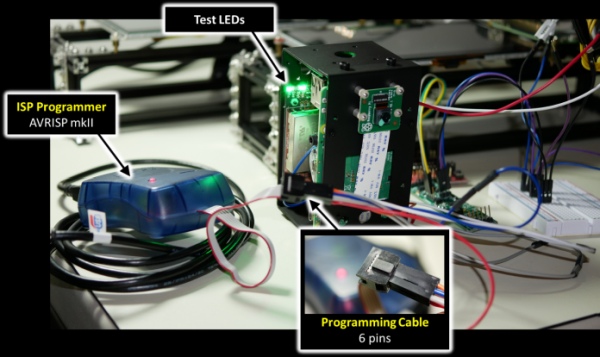
To upload a program, your ISP Programmer will need 6 wires connected to your ATTiny2313…
- VTG (usually this is +2.7 volts to +5 volts)
- GND (ground)
- MOSI
- MISO
- SCK
- RST
You can review how these wires are connected to the ATTiny2313 microcontroller in Figure 16 above.

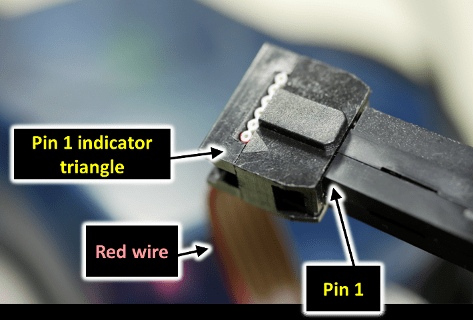
From Figure 20 above, you can see I have a 6-pin connector. This is where the ISP Programmer will connect to the ATTiny2313. This 6-pin layout is standard with Atmel’s ISP Programmers. If you have trouble figuring out which pin is #1, Atmel/Microchip will often mark pin #1 on their connectors with a triangle or a red wire.
With all 6 programming signals connected to the ATTiny2313, all we have to do now is:
- Connect the ISP Programmer’s USB port to the laptop/desktop
- Power on the custom circuit board (which will power on the ATTiny2313)
- Upload our C program using the ISP Programmer
Uploading the Application
With the coding and the wiring done, it is time to upload the program we just made. Connect the ISP Programmer to your computer’s USB port if you haven’t already, and make sure your ATTiny2313 is receiving power.
Back in Atmel Studio 7, access Device and Debugger Toolbar Options. This was a hammer-shaped icon with the default label of “None on.”
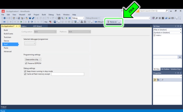
Clicking this area will launch the Debugger (Programming device) dialog.
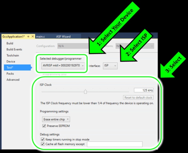
First, select your device as the “Selected debugger/programmer.” If you don’t see it listed, save your project, restart Atmel Studio 7, and then try to find it again.
Second, select Interface = ISP.
Finally, try the following settings:
- ISP Clock = 125 kHz or lower
- Programming settings = Erase entire chip
- Preserve EEPROM = Checked
- Keep timers running in stop mode = Checked
- Cache all flash memory except = Checked and blank
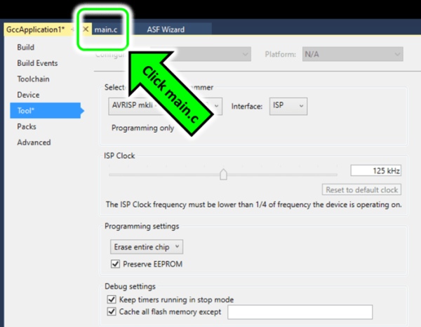
When you’re done, click the main.c tab at the top to return to the source code.
From here, the easiest way to upload the code is to start debugging by pressing the play button.
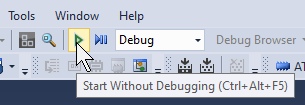
Within a few seconds, your LED should be blinking at 1 Hz!
Troubleshooting your Connection
If your code is not running, navigate to Tools –> Device Programming. This will launch the Device Programming dialog.
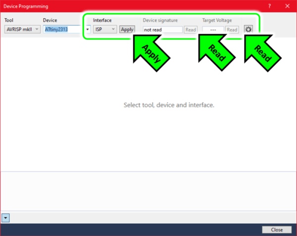
In the Device Programming window, you should be able to click “Apply,” “Read,” and “Read” again without encountering any errors.
Incorrect wiring (including rotating or mirroring the connector) is a common source of problems here. If you are able to hit the “Apply” button without an error, it means you can at least communicate with the ISP Programmer device, which is half the battle.
As a side note: Windows Device Manager should show your ISP programmer in the “Microchip tools” category.
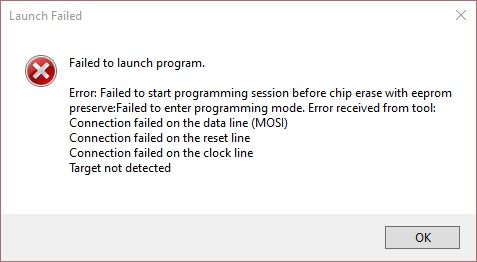
For me, a common mistake is connecting the 6-pin connector backward. Luckily, the AVRISP mkII is forgiving of this sort of mistake and didn’t take any damage. But you should double-check all 6 programming wire connections each time.
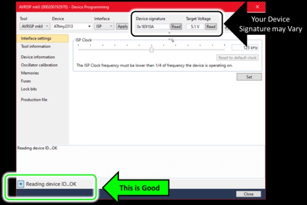
If you can read the device ID after adjusting your wiring, you are ready to retry debugging.
Closing Remarks
The Atmel microcontrollers—including the AVR family—emerged out of the technology boom of the mid 1990’s. These are 8-bit Reduced Instruction Set Computers (RISC). But more importantly, they were one of the first microcontrollers of the modern age to feature on-board flash memory.
Because of this and its low cost, the series remains relevant today, which is why I’ve chosen it here in the year 2020. Hobbyists, professionals, and educators use these devices extensively, even after Atmel was acquired by former competitor Microchip Technology. So you can definitely expect to see more devices like here in the future.
Important Notice: This article and its contents (the “Information”) belong to Unboxing-tomorrow.com and Voxidyne Media LLC. No license is granted for the use of it other than for information purposes. No license of any intellectual property rights is granted. The Information is subject to change without notice. The Information supplied is believed to be accurate, but Voxidyne Media LLC assumes no responsibility for its accuracy or completeness, any error in or omission from it or for any use made of it. Liability for loss or damage resulting from any reliance on the Information or use of it (including liability resulting from negligence or where Voxidyne Media LLC was aware of the possibility of such loss or damage arising) is excluded.
References
| [1] | Microchip Technology, Inc., “8-bit Microcontroller with 2 KBytes In-System Programmable Flash ATtiny2313/V,” Microchip Technology, Inc., Oct. 2016. [Online]. Available: http://ww1.microchip.com/downloads/en/DeviceDoc/Atmel-2543-AVR-ATtiny2313_Datasheet.pdf. [Accessed 8 July 2020]. |
| [2] | Microchip Technology, Inc., “AN2519 AVR® Microcontroller Hardware Design Considerations,” Microchip Technology, Inc., Feb. 2018. [Online]. Available: http://ww1.microchip.com/downloads/en/Appnotes/AN2519-AVR-Microcontroller-Hardware-Design-Considerations-00002519B.pdf. [Accessed 8 July 2020]. |
| [3] | Microchip Technology Inc., “Atmel Studio 7 | Microchip Technology,” Microchip Technology Inc., [Online]. Available: https://www.microchip.com/mplab/avr-support/atmel-studio-7. [Accessed 5 July 2020]. |
Source: Programming AVR Microcontrollers with Atmel Studio 7
- What is the main objective of this tutorial?
To download Atmel Studio 7, write a C program to blink an LED on a custom board using an ATTiny2313, and upload it via an ISP programmer. - Which microcontroller is used in the walkthrough?
The ATTiny2313 (an AVR 8-bit microcontroller) is used in the walkthrough. - Which IDE is recommended for programming the AVR in this article?
Atmel Studio 7 is the recommended integrated development environment. - What wires are required to connect the ISP programmer to the ATTiny2313?
VTG, GND, MOSI, MISO, SCK, and RST are required. - How does the example C program indicate success?
The program blinks a test LED attached to port B pin 4 (PB4) at approximately 1 Hz. - What must you be aware of before programming the microcontroller?
The procedure will erase any existing programs or bootloaders on the microcontroller. - What ISP interface setting should be selected in Atmel Studio?
Interface should be set to ISP in the debugger/programmer options. - What ISP clock speed is suggested for programming?
ISP Clock = 125 kHz or lower is suggested. - How can you verify successful communication with the ISP programmer?
Use Tools -> Device Programming, click Apply and Read; successful reads indicate communication and you can read the device ID. - What should you install alongside Atmel Studio during setup?
The Atmel Software Framework (ASF) and example projects are optional but can be installed; anti-malware is recommended.