Summary of Programming in the C language for the ATmega16 microcontroller
This article guides students through the complete process of developing embedded microcontroller software using C. It covers problem-solving methodologies, algorithm design, and flowchart creation to visualize logic before coding. The text details C programming fundamentals specific to microcontrollers, including preprocessor directives, variable types, constants, input/output operations, operators, control structures (loops, conditionals), functions for modularity, and arrays. Emphasis is placed on structured programming, documentation, testing via simulators or hardware, and adhering to standards for readability and efficiency in resource-constrained environments.
Parts used in the Embedded Microcontroller Software Development:
- Microcontroller (specifically Atmel AVR Family like ATmega16)
- C Programming Language Compiler
- Flowcharts (visual tools for algorithms)
- Atmel Data Sheets
- Sensors (for temperature and valve positions)
- Data Direction Registers (DDRn)
- PIN Registers
- PORT Registers
- Simulators and Emulators
- Laboratory Hardware
Introduction
“Programming is merely one facet of a more extensive puzzle. To effectively address a problem, programmers must thoroughly understand and navigate the entire problem-solving process before diving into software development. This platform will outline the essential steps for problem analysis and solution implementation.”
Following an introduction to the fundamental problem-solving process, this platform will proceed by addressing the additional tools essential for solution development. It will explore the creation of algorithms for tackling specific problems. The process of using flowcharts to help visualize these algorithms and facilitate their conversion into functional C software will be explained. Additionally, the site will provide comprehensive coverage of the C programming language as a means to execute solutions for the assigned tasks.
The C programming language boasts numerous benefits in contrast to assembly or other high-level programming languages. These advantages render C particularly well-suited for deployment with microcontrollers. Once C software has been composed, it needs to undergo a transformation process to generate the final software that is loaded into the microcontroller. Furthermore, adhering to specific standards during the software development process is essential. These standards serve to enhance the readability and maintainability of the software.
This platform will employ illustrative examples to elucidate the subjects under consideration. Furthermore, it provides a range of resources to assist in the creation of microcontroller software. These resources encompass excerpts from Atmel data sheets, insights into interrupts, numeral conversions, the ASCII character table, laboratory equipment, and choices for programming the microcontroller with the required source code.
This website is purpose-built to guide students through the entire process, but each individual section can also serve as a standalone reference. On the left-hand navigation pane, you’ll find a list of topics under the “C Programming” category. The intended sequence starts with the introduction (this page) and proceeds down the list, beginning with “Problem Solving.” This sequence continues until you reach the bottom of the list. The information in the “References” section is not intended to be part of the lessons covered on this site; it’s meant to serve as a quick reference for additional information that students may need. Additionally, the top banner contains links to other websites that students may wish to visit.
Software for Embedded Microcontrollers
Developing software for embedded microcontrollers presents a distinct challenge. Embedded systems are anticipated to function continuously, 24/7, 365 days a year, without any downtime. Consequently, software for microcontrollers demands the implementation of sound coding practices, comprehensive documentation, and rigorous testing procedures.
C programming language is a versatile, high-level programming language with a general purpose. While the C language wasn’t originally tailored for microcontroller use, its popularity in this domain stems from its capacity to facilitate structured software development and compile into highly efficient machine-level code.
The utilization of any high-level programming language abstracts the programmer from the intricacies of the underlying microcontroller hardware. In the case of C, the compiler handles tasks such as register allocation and memory access, liberating the programmer to focus on software-specific details rather than the intricate aspects of a particular microcontroller. This decoupling from the hardware also bestows the advantage of software portability, requiring minimal effort to adapt it for use on other microcontrollers.
C programming for microcontrollers encompasses distinct attributes not present in typical C implementations, necessitating even seasoned C programmers to invest time in the learning process. The primary contrast between a program designed for a PC and one for an embedded microcontroller lies in the fact that a PC program typically concludes and returns control to an underlying operating system. Embedded systems, on the other hand, lack an operating system, which means that embedded applications operate continuously without a defined endpoint. Embedded applications must constantly have tasks to execute, avoiding any idle periods.
Solving Problems
To develop a successful embedded application, it is crucial to comprehend and adhere to a predetermined series of steps for resolving the assigned problem. The problem-solving steps presented will be consistently applied throughout this website.
The initial step in the process is to grasp the nature of the inquiry. If the programmer encounters ambiguity or confusion regarding the task at hand, it is imperative to seek supplementary information. In practical scenarios, this might entail a comprehensive inquiry with the “customer” to uncover the necessary details. In this educational context, the instructor (whether in a laboratory or lecture setting) serves as the customer. Hence, the student should reach out to the instructor for additional insights to elucidate the question or problem statement. Without a clear understanding or a well-defined objective, devising a solution becomes a challenging endeavor.
Once a comprehensive understanding of the problem is acquired, the programmer should proceed to craft a strategic plan for problem resolution. It is crucial for the programmer to fathom the rationale behind each task to be undertaken. While a more detailed exploration of algorithm development is forthcoming in the next section, it is safe to assert that if a programmer cannot resolve the problem on paper, their chances of solving it solely through haphazard software coding are minimal, if not nonexistent.
Once an algorithm has been devised, the programmer must delve into the practical implementation. The algorithm might involve tasks like reading or monitoring the temperature of a process. This temperature monitoring device could necessitate specific control signals to regulate its operation. The programmer needs to have a clear understanding of the prerequisites and the sequence in which control signals should be executed. Achieving this may entail reviewing datasheets and conducting research on the components in use. Subsequently, this additional information is employed to customize the algorithm to suit the particular target microcontroller. In certain instances, some systems may not require external components, but the algorithm still demands adaptation to the microcontroller.
With the algorithm now tailored to the microcontroller, the subsequent phase involves creating a well-defined plan for implementing the solution. In this endeavor, flowcharts are employed as a helpful tool. Flowcharts serve as visual representations of the algorithm’s logical flow. The graphical symbols and structures depicted in the flowchart can subsequently be translated into software code. Beyond facilitating the software development process, the creation of flowcharts assists in pinpointing recurring steps or sequences of tasks within the software. Once identified, these tasks can be encapsulated as software functions or code segments, minimizing redundancy and promoting efficient program design. This concept aligns with structured programming principles, which will be explored more extensively in later discussions. Additionally, the act of flowcharting an algorithm serves as a form of documentation for the customer.
After all the preparatory work has been accomplished, the programmer is poised to commence the actual software writing phase, thus resolving the current problem. It’s common for many programmers, whether they are newcomers or seasoned professionals, to be eager to dive straight into this phase without diligently progressing through the preceding steps. As a programmer accumulates experience, they may find that they can expedite the preliminary steps and still achieve satisfactory outcomes. However, less experienced programmers should invest as much time as necessary in completing these preliminary stages. Thoroughly executing these preliminary development steps significantly simplifies the subsequent software writing process. This website primarily focuses on employing the C programming language to implement the solution. It’s worth noting that while C is not the exclusive option for software development, it’s the sole language employed in this particular course. Subsequent sections of this website will delve into the details of the C language.
The concluding phase of the development cycle involves testing and validating the software. In this step, the software must undergo practical testing. Software testing can be executed through various methods. Simulators and emulators, for instance, can be deployed to mimic the software’s behavior while monitoring variables and other parameters. This approach assists the programmer in identifying both minor and, at times, significant software bugs. While EET 209 employs a simulator, the principal testing will entail programming the physical microcontroller and assessing the software’s functionality using the available laboratory hardware. This hands-on approach enables the student to directly observe successful results
Complex software and even relatively straightforward programs may not produce the intended outcomes on the initial try. Occasionally, the programmer might need to revisit and reiterate previous stages of the problem-solving sequence to guarantee the ultimate achievement of desired results. One thing remains certain in the realm of software development: it is inherently an iterative process.
Similar to most challenges, addressing problems associated with software development becomes more manageable when the task is divided into smaller, more digestible components. Breaking down the software into these more manageable segments not only simplifies the process of writing the code but also streamlines the testing phase.
Flowchart Creation:
A flowchart is a visual depiction of an algorithm, typically limited to one page for simplicity. The fundamental shapes, which are displayed on the right, constitute the primary symbols employed on this website. In addition to these symbols, flow lines and arrows are utilized to signify the progression of the program through the sequential steps.
The Terminal symbol serves as the starting and concluding point in a flowchart. The Process symbol, on the other hand, is employed to depict a task that requires execution. This task might range from a straightforward operation like adding two numbers to a more intricate task, such as calibrating a piece of equipment. The Decision symbol functions as a representation of a pivotal juncture in the algorithm, signifying the point at which a decision must be made.
Structured flowcharts inherently possess a solitary entry and exit point, a fundamental characteristic enforced by structured programming principles. Flowcharts serve as a potent instrument in the process of translating an algorithm into software. This transition will gain clarity when we delve into the program control structures of the C programming language, which will be discussed in subsequent sections.
Flowcharts serve as valuable documentation tools. On numerous occasions, this author has found it necessary to create flowcharts for documentation purposes, particularly for software authored by different programmers.
Flowcharts are versatile tools not limited to software documentation; they can also effectively document various process flows. To illustrate, you can employ flowcharts to visually represent the problem-solving process:
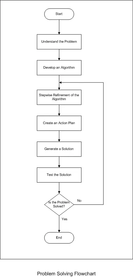
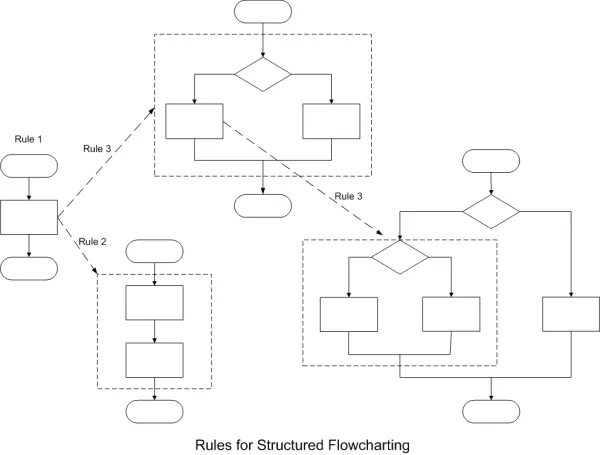
The flowchart depicted above represents the generation of a software solution as a single block. In reality, the process of creating a software solution is more intricate. As mentioned earlier, flowcharts often simplify processes by presenting them as single blocks. There are several structured flowcharting rules that can be employed. The initial rule emphasizes beginning with the simplest flowchart, similar to the one illustrated above. The second rule permits any process rectangle to be substituted with a sequence of processes. The third rule allows the replacement of any process with various control structures containing decisions and actions. These rules can be flexibly applied in any order and iterated as necessary. The subsequent diagram illustrates the application of these rules to a flowchart:
The flowchart presented below offers a more comprehensive depiction of the “Generate a Solution” process, as initially seen in the Problem Solving Flowchart. This Software Development Flowchart incorporates certain rules as previously described.
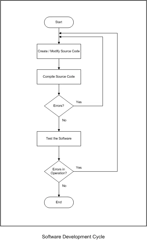
Both of the aforementioned flowcharts feature decision points located at the lower end of the flowchart. These decision points involve inquiries related to the software’s functioning or the overall solution. In situations where errors are identified in the software or the solution, the flow is redirected to a prior step. These preceding steps are subsequently revisited, refined, or adjusted in an effort to attain the intended outcome. The outcomes are continually tested, and the process iterates until the desired results are achieved.
The previously presented flowcharts delineate the procedures associated with problem-solving and software development. They indeed serve as effective illustrations of utilizing flowcharts to elucidate processes or algorithms. However, they do not represent the kind of processes implemented with a microcontroller. Consequently, we will revisit the algorithms discussed earlier in the Algorithm Development section. These processes align more closely with “real-world” applications that a programmer may need to address using a microcontroller.
Structure of the Program:
A basic embedded C program for the ATmega16 is shown below:

/*
Simple C program to illustrate the basic components of a program.
Written by:  Jeffrey J. Richardson, Purdue University, February 18, 2003

This program actually performs no tasks, calls no functions, and uses no variables
*/

#include<mega16.h>

void main(void)
    {

    while(1);            // stay here forever...never ending
    }
The majority of C programs are typically composed in lowercase letters. It’s worth noting that C is a case-sensitive language, which implies that the compiler does differentiate between uppercase and corresponding lowercase letters. Uppercase letters are typically reserved for constants often encountered in #define statements (which will be discussed later). Additionally, it’s a crucial convention in C that all C statements are concluded with a semicolon.
Preprocessor Commands:
C programs comprise both statements and directives. Directives are essentially commands given to the compiler. The preprocessor, which is a program, executes these compiler instructions before the actual C code is compiled. Among the most frequently employed preprocessor directives are the #include and #define directives.
The #include directive instructs the compiler to import the complete content of another file. Typically, the #include preprocessor directive is employed in conjunction with header files, denoted by the .h extension, which provide essential information about the microcontroller or library. When using the < > angle brackets construct in the statement, it signals the compiler to search in a predefined standard location or directory, usually an INC directory within the compiler’s primary directory structure. An alternative location can be specified using double quotes (” “) instead of the < > symbols. In this case, the compiler initiates the search in the current directory. If a different directory or even a different drive needs to be specified, the programmer must input the relevant path information. The following examples illustrate the use of double quotes to indicate a file located in the current directory.
#include “my_header_file.h”
The #define preprocessor is employed to establish a constant. A constant, as the name implies, is a value that remains unaltered throughout the program. Constants can be utilized to define, for instance, the maximum size of an element in the program or to enhance the code’s readability. The preprocessor essentially substitutes the text within the #define statement with the subsequent information. In most cases, it’s customary to employ uppercase letters for constants. For instance:
#define MAX_SIZE 256
value = MAX_SIZE; // use a Constant to load the variable
In the provided example, the line of code “value = MAX_SIZE” is modified by the preprocessor to “value = 256.” The term or constant “MAX_SIZE” gets substituted with the numeric value 256. Constants can also find utility in control statements. While control statements will be examined more thoroughly in subsequent discussions, the following example illustrates the fundamental concept.
#define MAX_SIZE 256
if ( current_value > MAX_SIZE) // Test the value against a known maximum limit
{
// code omitted for clarity
}
The Main( ) Function
Every C program incorporates at least one function, and that’s the main function. A function is essentially a program segment dedicated to executing a distinct task. However, the main function differs slightly from regular functions. Although we’ll delve deeper into functions in a subsequent section, one notable distinction between the main function and typical functions is that the main function is automatically invoked or executed as the program commences, while any other function necessitates a direct or indirect call from the main function. Consequently, the main function is often characterized as the initial task since it’s the first to execute when the program is launched.
Code Sections
Program structure plays a crucial role in the framework of program development. Structured programming serves as a method employed to structure program code systematically. Adopting a structured approach can facilitate the debugging process (identifying and rectifying code errors) and enhances the legibility of the source code.
A code block can be described as a set of statements enclosed by curly braces, creating a compound statement, and serving as the fundamental components of structured programs. A code block commences with an opening brace “{,” and concludes with a closing brace “}”. These braces delineate the code’s body or block and are used to encapsulate functions and various control statements. By indenting the code block—such as using a single tab space—the block of code becomes more prominent amidst the surrounding code segments. This practice enhances program readability and, subsequently, facilitates debugging. It’s advisable to establish and consistently follow a convention for code formatting throughout the program. The standard employed for all programs related to this site will be as described above, using one tab space for indentation.
While it’s not mandatory, positioning braces on separate lines can significantly enhance the source code’s legibility. It’s recommended that these braces align with the code block’s indentation. In the C programming language, so-called white spaces are disregarded. White spaces encompass characters lacking any discernible symbols. For instance, a space character merely creates a gap between letters, and a carriage return introduces a vertical separation between characters. The compiler disregards both types of characters. To the compiler, a curly brace at the start or end of a code line is equivalent to a curly brace occupying its own line. If the compiler interprets these various scenarios as identical, the difference primarily benefits human code readers. The primary objective is to compose code that is easily readable. Therefore, it’s recommended, for better code readability, to place the braces on separate lines. However, on occasion, curly braces might be situated at the beginning or end of a code line to potentially conserve paper when printing extensive programs.
void main(void)
{
while(1); // stay here forever…never ending
}
The provided code is excerpted from the introductory example in this section. It’s worth observing that the braces are both indented and positioned on separate lines within the code. This practice aids both the programmer and any other individuals reviewing the code in identifying the existence of a code block.
Comments
Comments serve as a valuable instrument employed by programmers to enhance the comprehensibility of software. The effective utilization of comments holds paramount significance in improving the source code’s legibility. Comments should enable the software to be effortlessly comprehended by individuals who might not possess familiarity with the software, or even by the original programmer at a later date. A distinguishing trait of a “good” program is its ability to be read and grasped by anyone, regardless of their programming knowledge. Well-commented code plays a pivotal role in achieving this goal.
Barnett, Cox, and O’Cull advocate for comprehensive commenting, suggesting that every line of code warrants a comment (with exceptions for truly self-evident aspects). They further emphasize that these comments should go beyond merely restating the instructions; instead, they should elucidate the instructions’ intent. It’s important to note that comments have no bearing on code generation. Consequently, comments do not induce the target microcontroller to execute any instructions; their sole purpose is to facilitate comprehension for those reviewing the software.
Comment blocks are indispensable at the outset of any function, encompassing the main function. In the case of the main function, the comment block resides at the very beginning of the source code. For other functions, it’s recommended to place a comment block immediately preceding the function declaration. This comment block should encompass essential details, including the function’s name, its purpose, the programmer’s name, the function’s creation date, the names of other functions it might call, references to global variables used, and explanations for local variables. The previously mentioned list serves as a sample of the type of information that should be integrated. It’s important to note that this list isn’t rigid, but it does provide a foundation for the sort of information that should be included. The following illustration offers an example of a comment block positioned prior to a function:
/*
Routine: init_lcd
By: Jeffrey J. Richardson
Date: Jan. 17, 2003
Description:
Routine that will initialize a two line LCD.
The cursor is on, non-blink, cursor style is an underscore.
The display is configured to shift the cursor right after each character.
No local or global variables are used.
Functions Called:
delay_ms
putcmd_lcd
*/
Comments are classified into two distinct styles. The first type corresponds to the aforementioned block comment. Block comments are enclosed by an opening comment marker, represented as a forward slash followed by an asterisk /*, and a closing comment marker, denoted by an asterisk followed by a forward slash */. All content sandwiched between these opening and closing markers is disregarded by the compiler. Contemporary compilers often modify the text’s color within the markers to indicate that this information constitutes a comment.
The second category of comments is the single-line comment, recognized by two forward slashes //. Such comments extend until the conclusion of the source code line, which is typically indicated by a carriage return and linefeed.
A note of caution: When a backslash is placed at the end of a line of C code, it instructs the compiler to combine the subsequent line of code with the current line. This bears implications if the programmer inadvertently leaves a backslash at the end of a single-line comment. In such a scenario, any potential line of C code following the comment will be treated as part of the comment and will not be compiled as an integral part of the software. Although the graphical user interface (GUI) might distinguish comments with a distinct color, it may not highlight this condition, potentially eluding the programmer’s notice.
y = mx + b; // solve for the y value in this system \
printf(“The y intercept is %d\n\r.”, y);
Avoid delving too deeply into the particulars of the preceding example; it’s purely intended to demonstrate that the backslash located at the end of the comment line communicates to the compiler that the print statement is a component of the comment. Consequently, the print statement will never be executed because it isn’t genuinely part of the code, resulting in the program not functioning as intended.
Variables and Constants
Variables
Typically, embedded microcontroller programs are designed to receive input data, execute various operations or manipulations on it, and generate an output dependent on both the input and the performed operations. Variables play a pivotal role in this process by storing information in the microcontroller’s memory, enabling the programmer to access and reference them using meaningful names.
To make a variable usable, it must first be declared, specifying both its data type and its given name. C programming is case-sensitive, which means it distinguishes between lowercase and uppercase letters. It’s generally advisable to avoid using capital letters in variable names, as these are often reserved for constants (which we’ll discuss shortly). Employing meaningful and descriptive names for all variables is of utmost importance when crafting readable software. Descriptive names enhance software comprehension. When selecting variable names, they should be as detailed as necessary to convey the variable’s function. However, it’s essential to limit the variable name’s length to a maximum of 31 characters. Variable names must commence with a letter, but the subsequent characters can consist of letters, numbers, and underscores.
Variables can be defined at the onset of any code block, although it’s customary to declare them primarily at the outset of functions for local variables. These declarations should be positioned after the opening (left) brace and before any executable statement within the block. You can declare multiple variables of the same data type in a single line by separating their names with a comma. To enhance readability, it’s advisable to follow any separating comma with a space.
void main(void)
{
unsigned char number_of_pulses; // variable to count pulses
unsigned int loop_cntr, count_value; // variables for loop control
// omitted code for clarity
}
Variables can be assigned initial values as part of their declaration. To initialize a variable, simply place an equal sign after the variable name, followed by the desired initial value. It’s important to note that if no explicit initialization is provided, the CodeVisionAVR compiler will automatically set variables to zero.
unsigned char number_of_pulses = 100; // variable to count pulses
When multiple variables are declared in a single line, they can also be initialized to the programmer’s preferred values. Nevertheless, such an approach might result in less readable code. Hence, the following recommendation is proposed: When initializing variables upon declaration, allocate each variable its line of code. For instance:
unsigned int loop_cntr = 25, count_value = 100; // variables for loop control
may be easier to read as:
unsigned int loop_cntr = 25; // variable for the control loop
unsigned int count_value = 100; // variable for counting
Global vs. Local Variables:
In C code, there are two fundamental types of variables. First, a local variable is declared within a function’s body and is accessible only within the scope of that function. Most local variables are created when the function is invoked and cease to exist when the function concludes. However, if there is a need to retain the value stored in a local variable after the function has completed its execution, the static variable type can be employed. Static variables persist beyond the function’s termination; their values are retained. Static variables can be initialized like any other variable, but this initialization is executed only on the first invocation of the function.
The provided illustration exemplifies the generation of local variables within the main function of the software. These variables have scope exclusively within the main function and are not valid outside of it.
The second category of variables employed in C code is the global variable. Global variables are defined outside of any functions, typically placed at the beginning of the source code after any preprocessor directives, and they are accessible to all functions within the program. Introducing global variables augments the intricacy of the software and can introduce complications during code debugging. A general guideline is to resort to global variables only when their necessity is unequivocal. Here’s an example of declaring global variables:
/*
Simple C program to illustrate Global variables
Written by: Jeffrey J. Richardson, Purdue University, March 22, 2003
This program actually performs no tasks, calls no functions, and uses no variables
*/
#include<mega16.h>
unsigned char global_ch; // global character variable for storing serial information
unsigned int int_counter = 0; // global counter for use in the interrupt routine
void main(void)
{
// code omitted for clarity
}
Variable Types and Selection
|
Type |
# of bytes | # of bits | Minimum | Maximum |
| bit | – | 1 | 0 | 1 |
| char | 1 | 8 | -128 | 127 |
| signed char | 1 | 8 | -128 | 127 |
| unsigned char | 1 | 8 | 0 | 255 |
| int | 2 | 16 | -32,768 | 32,767 |
| signed int | 2 | 16 | -32,768 | 32,767 |
| unsigned int | 2 | 16 | 0 | 65,535 |
| long | 4 | 32 | -2,147,483,648 | 2,147,483,647 |
| signed long | 4 | 32 | -2,147,483,648 | 2,147,483,647 |
| unsigned long | 4 | 32 | 0 | 4,294,967,295 |
| float | 4 | 32 | 1.28E-38 | 3.4E38 |
The Atmel AVR Family of microcontrollers falls within the category of eight-bit microcontrollers. Consequently, the default data type for all variables should be a single-byte character, unless the variable’s size requirements necessitate a larger data type. The judicious choice of variable size is of paramount importance for the proper functioning of microcontroller software. An inappropriate data type selection can lead to inaccuracies or undesired outcomes and potentially hamper the code’s execution speed. Furthermore, it’s worth noting that Atmel microcontrollers are not explicitly tailored for performing signed mathematical operations. Therefore, it’s advisable to use variables of the unsigned data type unless they are explicitly required for signed operations.
Reflecting on Example 1 from the section on algorithm development: To appropriately choose the data type for the variable containing the total value, the programmer must have an understanding of the potential size of the result. The problem’s premise involves adding the numbers 17, 20, 1, 22, and 18, resulting in a decimal value of 78. In this scenario, a character-sized variable suffices to hold the resulting value. However, if the problem description indicated that the input range for the five numbers spanned from 0 to 100, the total value could potentially reach 500. An unsigned character can only accommodate values from 0 to 255. Consequently, for this “new” total, a variable of the integer data type would be required, as it can cover a broader range. Once again, given the program’s nature, where it doesn’t engage in signed operations, opting for an unsigned integer variable is advisable.
The microcontroller’s architecture operates at its highest efficiency when handling character-sized variables (8 bits). Therefore, it’s advisable to employ a character-sized variable whenever feasible to optimize the program’s execution speed. Using a 16-bit integer variable, in contrast, can necessitate the microcontroller to execute approximately twice as many instructions to manage the variable compared to an 8-bit value. Nevertheless, in cases where a 16-bit value is indispensable, the programmer has no alternative but to utilize an integer.
It is also crucial for the programmer to monitor intermediate data sizes. This can be best demonstrated using the second example from the algorithm development section. In this example, the task involves computing the average of six numbers. To calculate the average, the sum of these numbers must be determined at some point. If we modify the problem statement to specify that the input numbers can fall within the range of 0 to 50, it might seem that unsigned character variables would suffice to store the results, given that all values are below 50.
However, it’s entirely possible for the sum of the six numbers to exceed the maximum limit of an unsigned character. For instance, consider the numbers 48, 49, 47, 49, 48, and 50; their intermediate sum totals 291. This value surpasses the capacity of a character-sized variable. Attempting to store it in such a variable leads to an inaccurate outcome. The inaccuracy arises because 291 is crammed into an 8-bit variable, whereas it actually requires 9 bits to be accurately represented. Forcing the value into an 8-bit variable causes the loss of the most significant bit, as there’s no place to store it. Consequently, using an 8-bit variable to hold the result of the aforementioned six numbers yields the value 35. Clearly, 35 is not the correct total of those numbers. Consequently, dividing 35 by 6 would result in an average between 5 and 6, rather than the accurate range of 48 to 49.
Looking inside the numbers:
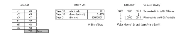
The example mentioned above also underscores a critical aspect of mathematical operations and microcontroller data types: integer math. Integer math doesn’t involve decimal points, as is the case with floating-point math. In integer math, the results are truncated to whole numbers without rounding. Revisiting the example provided, when we divide 291 by 6, assuming floating-point math, the result is 48.5. However, since the example uses character and integer variables (not floating-point), the result is truncated to 48, rather than 48.5, as it would be if appropriate variable sizes were used. If only character-sized variables were employed, dividing 35 by 6 would yield 5.833, which is truncated to 5. Thus, integer math is a crucial concept to consider when choosing data types for a program.
When precision is essential, and the application demands the accuracy of floating-point math, the programmer can opt to use the float data type. However, it’s important to note that employing floating-point variables will require the microcontroller to execute floating-point math operations. As Atmel microcontrollers are not optimized for floating-point math, this will introduce additional processing overhead, slowing down their operations due to the extra instructions needed to achieve floating-point results. Therefore, programmers should be mindful of the software’s precision requirements and utilize floating-point variables only when they are absolutely indispensable.
Occasionally, programmers may only need to track a single bit, often referred to as a flag. This bit can be declared in the same way as any other variable, using the data type ‘bit,’ which can take on values of either 1 or 0.
Constants
Constants are essentially the textual representation of a numerical value. They can take various formats, including decimal and hexadecimal. Typically, constants are generated using the #define preprocessor directive, as explained in the Program Structure section. In the case of lengthy constants, it’s a common practice to append a trailing ‘L’ to indicate their length. Constants serve the purpose of making the software somewhat adaptable and enhancing its readability.
#define XTAL 6000000L
As an illustration, consider the #define preprocessor directive: #define XTAL 6000000L. This directive permits the programmer to use the name XTAL to represent the value of the crystal oscillator. If, at some point, the crystal frequency needs to be modified after the software has already been developed, altering the preprocessor directive will effectively update the clock frequency value throughout the program.
I/O Operations
As previously discussed in the section on variables, microcontroller programs are primarily designed for tasks involving input data acquisition and output control. This section focuses on the first and last aspects: acquiring input information and managing microcontroller outputs. The segment covering data manipulation will commence in the following section, which discusses “Expressions.”
Sensory inputs play a pivotal role in any embedded system. A device must first recognize the necessity for a particular action before determining the specific course of action to be taken, followed by the execution of those actions. An embedded microcontroller’s role might include monitoring and regulating a process’s temperature. In such a system, the microcontroller must possess the capability to both “perceive” the process temperature and manipulate it.
Input Operations
For an embedded microcontroller to effectively make informed decisions, it must have the capability to interact with its surroundings, or at least access the essential data required to make those decisions. Referring back to the previous example, consider the microcontroller’s need to monitor the process temperature and possibly the positions of control valves. The intricate workings of these sensors are not our immediate concern. Instead, our focus is on understanding how this data is interfaced with the microcontroller, enabling it to initiate appropriate actions.
The precise allocation of ports for temperature monitoring and valve position sensing is not of primary importance within this discussion. Nonetheless, an allocation must be made. Thus, for our purposes, let’s assume that temperature will be monitored on Port A, while valve positions will be tracked on Port B and Port D.
The Atmel AVR Family of microcontrollers mandates that ports are configured as either input or output. Each port possesses a data direction register, which governs the direction (input or output) of the respective port. For a more in-depth understanding of how to configure ports for input and output, please refer to the “Configuring Port for Input or Output” resource, which can be accessed by navigating through the Atmel Resources link. To open the detailed description in a separate window, click here.
The principal register that concerns us for configuring the port’s data direction is the DDRn register, where ‘n’ represents a general naming convention shared by multiple registers. By substituting ‘n’ with the capital letter corresponding to the desired port, you can access the appropriate data port direction register. For example, replacing ‘n’ with ‘A’ allows you to control the data direction register linked with PORTA. To configure the entire port for input, set the data direction register to zero. This can be achieved with the following line of code: DDRA = 0;. This code must be repeated for PortB and PortD, resulting in the following three lines of code:
DDRA = 0; // set PortA for Input
DDRB = 0; // set PortB for Input
DDRD = 0; // set PortD for Input
Once the data ports are set up as inputs, the microcontroller becomes capable of reading sensor data. To retain and utilize this information at a later stage, we need to create three variables to store the sensor values. (A comprehensive discussion on variables was presented in a previous section. If needed, you can revisit that information.) Given that microcontroller ports are 8 bits in width, it’s suitable to employ character-sized variables to hold these values. Considering that we won’t be dealing with negative temperatures, we opt for unsigned character type variables. Here are the variable declarations:
unsigned char water_temp; // 8-bits for the actual temperature
unsigned char hot_position; // 8-bit variable to store the hot position
unsigned char cold_position; // 8-bit variable to store the cold position
With the data direction registers configured as inputs and variables in place to store data from the sensors, the values are now prepared for reading. A critical point to bear in mind when reading inputs is the specific register name from which the data must be retrieved. The actual input data is extracted from the PIN register associated with each port. To collect data from the input pins on PortA, you employ the following instruction: water_temp = PINA;. This fundamental structure is reiterated for each value that necessitates reading. To illustrate, the subsequent three lines of code are used to acquire the sensor values:
water_temp = PINA; // get the actual faucet water temperature
hot_position = PINB; // get the hot water position
cold_position = PIND; // get the cold water position
Output Operations
After the microcontroller has gathered the necessary information and made a decision, it’s time to initiate the suitable action or actions. This typically entails generating some form of output. In this course, microcontrollers provide low-current TTL-compatible output signals. If needed, these signals can be amplified to different voltage levels and current ratings, but such details are addressed in a separate course. Referring back to the earlier example, we’ll presume that the task can be achieved by turning on or setting an output to a specific logic level.
Before a port can serve as an output, you must configure the corresponding data direction register for output mode. This process is similar to configuring a port for input, with the only difference being the value written to the data direction register. While writing a zero to the data direction register sets the port for input, writing a logic one is necessary to set the port as an output. In the case of PortC, setting DDRC to all ones configures the 8 bits of the port for output. The value to be written to the direction register is the binary number 11111111, which can also be represented as the hexadecimal number 0xFF. You can use the following C statement to assign this value to the data direction register: `DDRC = 0xFF;`. This line of code should be added along with the previous lines for configuring the input ports, and don’t forget to include a comment explaining the purpose of the statement. These four statements are presented together below:
DDRA = 0; // set PortA for Input
DDRB = 0; // set PortB for Input
DDRD = 0; // set PortD for Input
DDRC = 0xFF; // set PortC as an Output
To control a device, you can set the corresponding port pin to either a logic high (1) or logic low (0) by writing the appropriate values to the PORT register associated with the relevant port. In the current example, you need to write output data to PORTC. The data written to the port can either be sourced from a variable or from a constant value defined within the software. To transmit data to the output pins of the port, you can utilize the following statement: `PORTC = 0x00;`. In this instance, the example demonstrates the constant value 0 being written to the output port. The example provided below illustrates a scenario where the output value is derived from a previously declared variable.
unsigned char water_temp; // 8-bits for actual temperature
unsigned char hot_position; // 8-bit variable to store the hot position
unsigned char cold_position; // 8-bit variable to store the cold position
unsigned char output_value; // 8-bits for output control
PORTC = output_value; // place the value stored in the variable on PortC
C Operators
C operators serve as the means by which various mathematical operations and evaluations within a program are executed. These operators are represented by symbols that instruct the compiler to carry out specific types of data manipulation or assessments. These assessments involve tasks like verifying equality between values or ascertaining whether a given value is greater or lesser than another value. Data manipulations encompass mathematical computations such as addition, subtraction, multiplication, or division of numbers. Additionally, data manipulations include Boolean operations like logical AND and OR operations performed on data bits. The C operators can be classified into five distinct categories: Relational, Arithmetic, Assignment, Logical, and Bitwise Operators.
Assignment Operators
In programming languages, there is a need for a mechanism to assign constant values to variables and registers, and the C language is no exception. This task is carried out by the assignment operator, which is typically represented by the equal sign. The assignment operator serves a dual purpose—it assigns constant values to variables and registers, and it can also be employed to copy values from one variable to another.
| Operator | Description |
| = | Assignment |
| Given: | Results: |
|
Assign the value 25 to the variable num. |
num = 25; |
|
Assign the value in the variable num to the variable old_num. |
old_num = num; |
Relational Operators
Relational Operators, as the name suggests, serve the purpose of determining the relationship between values or variables. These operators enable the evaluation of equality as well as greater than or less than comparisons, and they also allow various combinations of these conditions. Typically, relational operators find their primary usage within control structures.
Relational operators offer the capability to assess whether two values are equal or not, and they also enable the comparison of two values to determine if one is greater than or less than the other. In addition, a subset of these operators permits the amalgamation of equality and magnitude comparisons, enabling the program to evaluate if a value is either equal to or greater than another, or if it’s less than or equal to a specific value.
The outcome of a relational operation is a binary result, where it’s either True or False. In the C programming language, a false condition is denoted as having a value of zero. Conversely, a true condition is essentially defined as anything that is not false, in other words, a non-zero value.
| Operator | Description |
| == | Equal to |
| != | Not equal to |
| < | Less than |
| > | Greater than |
| >= | Greater than or equal to |
| <= | Less than or equal to |
| Given: | Evaluate: | Results: |
|
x = 9, y = 16 |
x == y | False |
| x != y | True | |
| x > y | False | |
| x < y | True | |
| x >= y | False | |
| x <= y | True |
Arithmetic Operators
Arithmetic Operators provide the program with the capability to execute fundamental mathematical operations. These operations encompass addition, subtraction, multiplication, and division. Additionally, the set of arithmetic operators includes modulus, increment, and decrement instructions.
Performing addition, subtraction, multiplication, and division in a computer program adheres to the elementary mathematical principles familiar to most individuals. The modulus operator is linked to division since it yields the integer remainder resulting from the division of two numbers. Increment and decrement operations are akin to increasing or decreasing a value by one. These operations essentially provide a convenient way to add or subtract one.
| Operator | Description |
| + | Addition |
| – | Subtraction |
| * | Multiplication |
| / | Division |
| % | Modulus |
| ++ | Increment |
| — | Decrement |
| Given: | Evaluate: | Results: |
|
x = 12, y = 3 |
x + y | 15 |
| x – y | 9 | |
| x * y | 36 | |
| x / y | 4 | |
| x = 10, y = 3 | x % y | 1 |
| x++ | 11 | |
| y– | 2 |
Logical Operators
The outcome of a logical operation is binary, representing either true or false. As previously defined, false equates to a value of zero, while true is a non-zero value. Logical operators consider multi-bit values or variables as a unified entity. These operators include logical AND and logical OR and are often used in conjunction with relational operators to formulate compound statements.
In the case of the logical AND operator, all the relational operations within it must evaluate to true for the result to be true. A single false component in a logical AND statement renders the entire statement false. Conversely, the logical OR operator necessitates only one true result among the conditional or relational operations to render the entire statement true.
| Operator | Description |
| && | Logical AND |
| || | Logical OR |
| Given: | Evaluate: | Results: |
| x = 8 | ( ( x >= 8 ) && ( x <= 15) ) |
True |
| x = 12 | ( ( x == 10 ) || ( x == 18 ) ) |
False |
Bitwise Operators
Bitwise operators are concerned with the manipulation of individual bit positions within values of interest. The result of an operation on one bit is entirely isolated from other bit positions. Bitwise operators are commonly employed to inspect, set, or clear individual bits. These operators are closely aligned with the operations executed by discrete digital systems, encompassing bitwise AND, OR, Exclusive OR, and Complement. Additionally, bitwise operators offer functionality for shifting bits either to the right or left.
To perform bit testing, the AND operation is employed in conjunction with a “mask.” A mask is a value with a “1” in the desired bit position. If the bit of interest is set to one, the result of the operation will be a non-zero value. Conversely, if the bit of interest is zero, the bit test’s result will be zero.
Clearing a bit is achieved by employing the bitwise AND operation. To clear a bit, insert a “0” in the bit position of interest within the mask. Executing the bitwise AND operation will result in the specified bit being cleared, or set to zero. To prevent the clearing of any unwanted bits, you must set their respective bit positions to one.
To set a bit, you should position a logic one in the bit’s designated location within the mask. Subsequently, perform a bitwise OR operation with the value or variable that requires the bit to be set to a high value. It’s important to ensure that any bits not intentionally being set in the mask are set to zero to avoid unintentional bit setting.
Shifting bits, whether to the left or right, is highly valuable for data manipulation. These operations enable data to be divided into smaller, more manageable segments. Additionally, shift operations are employed to combine smaller fragments of information, generating a larger, unified value from individual components.
When utilizing any of the Bitwise operators, it is strongly advised to enclose the operation within parentheses.
| Operator | Description |
| & | AND |
| | | OR |
| ^ | Exclusive OR |
| << | Shift left |
| >> | Shift right |
| ~ | Complement |
| Given: (values in binary) | Evaluate: | Results: |
|
mask = 10000000, value = 10101010 |
( value & mask ) | 10000000 |
| mask = 10000000, value = 01000000 | ( value & mask ) | 00000000 |
| output = 00000010, value = 01010000 | ( value | output ) | 01010010 |
| output = 00000011, value = 00000010 | ( value | output ) | 00000011 |
| mask = 01010011, value = 10101111 | ( value ^ mask ) | 11111100 |
| value = 00001100 | ( value << 3 ) | 01100000 |
| value = 01100010 | ( value >> 4 ) | 00000110 |
| value = 01100101 | ( ~value ) | 10011010 |
Control Statements
Introduction:
Microcontrollers are typically employed to execute tasks that involve decision-making and intelligence. The ability to make decisions and act upon them is fundamental to intelligence. In the C language, control statements are employed to make decisions and regulate the program’s flow based on the outcomes of these decisions.
Program Blocks and Loops:
A program block is defined by two key characteristics: it features a single entry point and a single exit point. At the core of a loop is a program block, which serves the purpose of iteratively executing an operation or a block of code based on a conditional expression.
Conditional expressions were thoroughly discussed in the C operators section. The crucial point to keep in mind is that a false condition is represented by a value of zero, and conversely, a true condition is defined as “not false.”
The proper use of braces and indentations are important to maintain readable code.
Control Structures:
The C language encompasses control statements such as if/else, do/while, while, for loops, and switch/case. The choice of which control structure to employ dictates how many times the statements or code block will be executed, if executed at all. This section will introduce and apply these control statements to carry out practical tasks that infuse “intelligence” into the software. These control statements empower a block of code to execute once, repeatedly, a specific number of times, or potentially be skipped entirely. The adept utilization of these control structures is fundamental in crafting well-structured software. By nesting control structures, it becomes possible to create more intricate and sophisticated software.
Structured programming is a methodology for structuring and coding programs to reduce complexity, enhance clarity, and simplify the processes of debugging and making modifications. The advantages of structured programming are outlined as follows:
- Operation is simple to trace
- Structures are self-documenting
- Structures are easy to define in flowcharts
- Structured programming increases programmer productivity
- Structures lead to functions
Item number 3 mentioned earlier pertains to flowcharts, which serve as visual depictions of algorithms. A well-constructed flowchart is an essential instrument for determining the correct control structure.
IF / Else:
The IF/ELSE statement can be likened to a “fork in the road,” as it steers the software’s course based on the outcome of the conditional expression. In an if statement, the conditional expression compares two values. When the conditional expression holds true, the “true” block of code is executed. Conversely, if the conditional expression is assessed as false, the else branch or code block is executed. It’s important to note that it’s common to have the microcontroller perform no action when the condition is false, making the else condition optional.
The flowchart for both an IF and an IF/ELSE structure is depicted below. What sets apart an IF statement from other control structures is the program’s subsequent path following the decision and its corresponding process. In either an IF or IF/ELSE structure, the program’s flow proceeds downward on the page.
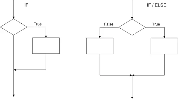
if (the conditional expression is true)
{
perform these statements
}
else
{
perform these statements if the conditional is false
}
While Loop
Within a While Loop, the expression is assessed when the program enters the beginning of the loop. If the expression is found to be true, the statements within the loop are executed. Once the program reaches the end of the code block, it returns to the start of the loop, and the condition is re-evaluated. This process continues as long as the condition remains true. If the condition becomes false, the code block is bypassed. The corresponding flowchart for a While Loop is presented below.
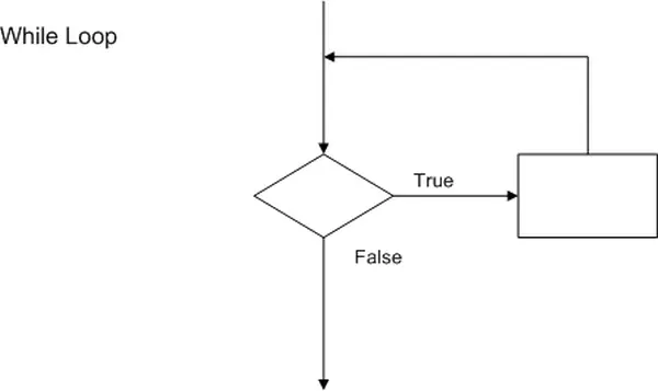
while (some conditional expression is true)
{
perform the statements located between the braces
}
DO / While
The Do/While loop bears a strong resemblance to the while loop. The primary distinction lies in the fact that the expression or condition is evaluated at the end of the loop. Consequently, the loop’s body is executed at least once, irrespective of the condition’s outcome. If the condition proves to be true, the loop body is executed again. This cycle continues until the condition is appraised as false.
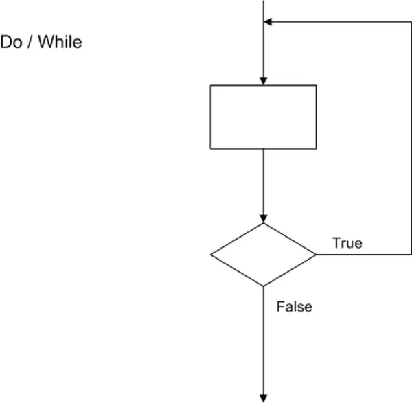
do
{
perform the statements located between the braces
} while (this conditional expression is true)
The while and do/while loops find common application in control-type scenarios, often employed to monitor specific inputs or registers.
For Loop:
The For Loop is conventionally used for executing a specific task or repetitive action a predetermined number of times, essentially serving as a count-controlled loop. This loop comprises an initial condition, a conditional expression, a modifier, and the code block or body. When the for loop is encountered, it starts with the execution of the initial condition. The conditional expression is then assessed to determine if it’s true or false. If the conditional is found to be true, the code block is executed. Upon reaching the end of the loop, the modifier is invoked. Program control is subsequently returned to the conditional statement, which is re-evaluated. If it remains true, the code block is executed again. This cycle persists, with the modifier being invoked each time the code block is completed, until the conditional becomes false.
The flowchart for a For Loop is displayed below. The general structure of the flowchart is akin to that of a While Loop. What distinguishes it as a For Loop is that the initial condition, conditional expression, and modifier all pertain to the same variable.
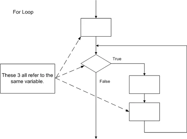
for ( variable initialized ; conditional expression ; variable modifier )
{
perform these statements while the conditional expression is true
}
The similarities between the For Loop and While Loop extend beyond the visual resemblance in flowcharts. In reality, any For Loop can be substituted or replicated using a While Loop. However, it’s important to note that not all While Loops can be substituted with a For Loop.
Switch / Case:
The Switch Case structure resembles a series of if statements and can include a default condition that is executed when none of the statements match. It is employed when there is a need to select one statement from multiple options.
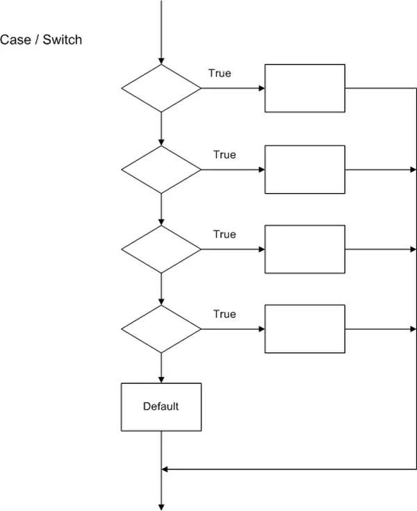
switch ( variable of interest )
{
case value1:
code to be executed.
break;
case value2:
code to be executed.
break;
case value3:
code to be executed.
break;
.
.
.
default:
code to be executed.
break;
}
Choosing the proper control statements:
Selecting the right control structure is essential for ensuring the software’s proper operation and enhancing its readability. Flowcharts serve as valuable tools for choosing the appropriate control structure as each one exhibits a unique program flow, evident in the flowchart. Flowcharts play a crucial role in translating an algorithm into C code.
All control structures share the common element of decision-making within their flowchart. The arrangement of processes around this decision point helps determine the type of control statement. Another significant aspect for identifying the control structure is the direction of flow within the processes. For instance, While, DO/While, and For Loops guide the flow back to the top of the flowchart, whereas IF/Else and Case/Switch structures lead the program flow toward the bottom of the flowchart.
Functions:
A fundamental concept integral to high-level languages is the concept of functions. While they might be termed subroutines or procedures in other languages, the core idea remains consistent. In C, a function is a set of C language instructions that typically carry out a task more intricate than any inherent in the C language itself. In essence, a function executes a series of operations or statements that are too intricate to be achieved through a single line of C code.
Modular Software Through Functions
Functions can be likened to shorthand for lengthy and, at times, intricate sequences of commands. They have the capacity to invoke other functions, adding to the program’s organization and structure. Nevertheless, it’s imperative that a function isn’t overly complicated to the point of being unintelligible. Functions provide a means to modularize a program, breaking it down into more manageable segments. Any sequence of operations executed repeatedly is a suitable candidate for conversion into a function. By encapsulating code within a function, it becomes executable from various parts of a program simply by invoking the function.
Function Usage
There are various reasons for incorporating functions into a program. Utilizing functions effectively enhances the program’s readability and comprehensibility. It also promotes software reusability by enabling the use of established functions as foundational components for constructing new programs. Furthermore, employing functions helps eliminate redundant code within a program, yielding several advantages. Code housed within functions is simpler to update and maintain, and it follows a divide-and-conquer approach that streamlines program development.
The effective utilization of functions enhances program readability significantly. Employing descriptive function names that accurately represent their purpose is essential. This practice enables the programmer to streamline multiple operations into a single function call. Functions serve to keep the main code of the software uncluttered and easily maintainable. They almost serve as self-documenting elements within the code, reducing the need for excessive comments (though not entirely). Essentially, any process block in a simplified flowchart can be considered a potential candidate for encapsulation within a function. In other words, any process within a simplified flowchart that can be replaced by a sequence of processes or control structures qualifies as a suitable candidate for function implementation.
Leveraging the reusability of software blocks or functions offers numerous advantages. First and foremost, it streamlines program development. By incorporating a previously created and tested function, programmers save valuable time. They can integrate the function into the program with a high level of confidence that it will function as expected, reducing the need for debugging.
Function reuse further diminishes the software’s overall size. By designing functions with repetitive code segments, the program’s footprint is minimized, potentially freeing up precious memory space within the microcontroller. Embedded microcontrollers frequently operate within strict program memory constraints that necessitate efficient management. Functions enable the execution of a consistent set of instructions from multiple locations within the program. It only requires a single definition of the function, which can then be invoked as many times as needed.
Should the need for software modifications arise, having the code compartmentalized into functions can significantly streamline the process. Functions empower the programmer to implement necessary alterations in a single location, thereby effecting changes across multiple instances throughout the software. In essence, if a function is invoked five times within the software, modifying the function once will automatically affect all five processes that utilize it.
In the case of longer programs or projects involving multiple contributors, modular programming proves to be more advantageous. This approach entails dividing the software development into individual modules, which are subsequently interconnected or integrated to constitute the complete program. By employing this method, the program can be disassembled into functions and allocated among various developers.
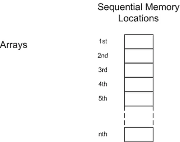
Arrays
An array can be defined as a basic assembly of closely related values. Essentially, an array represents a set of variables that possess a shared reference name and the same data type.
Arrays Defined
An array consists of variables with the same data type that are identified by a common name. Arrays are allocated in contiguous memory locations within the microcontroller’s memory. These arrays can be stored in either the volatile RAM section of memory or the non-volatile Flash memory of the microcontroller.
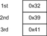
Before using an array, it needs to be declared, just like any other variable. Arrays can be declared using any data type available in the C programming language. However, arrays require an extra parameter in comparison to regular variables. This additional parameter is the array’s length, representing the number of elements to be stored in it.
unsigned char array[ 10 ]; // character array with 10 element
The individual elements of the array can be initialized when declaring the array, similar to other variables. You can set the initial values for the array elements by enclosing them within curly braces and separating the values with commas.
unsigned char ch_array [ 3 ] = { 0x32, 0x39, 0x41 }; // init the array elements
Arrays are employed in situations where collections of related information need to be managed as a single unit. Arrays find applications in various scenarios, such as serial queues, data stacks, and control words. Data arrays are frequently utilized as lookup tables.
Array usage
An array is accessed using an index enclosed within square brackets. It’s important to note that arrays begin with an index of zero, and the highest index number is derived by subtracting one from the total number of elements in the array.
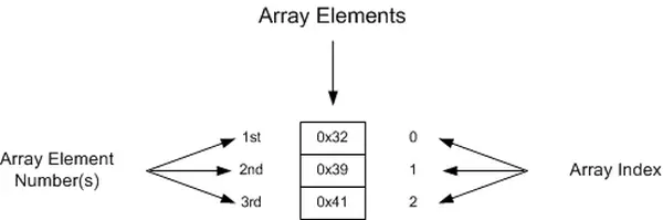
value = ch_array[ 0 ]; // places the number 0x32 into value
The array shown above is accessed using the explicit index value of 0. However, arrays are frequently accessed using a variable as the index, as demonstrated below:
unsigned char index = 2; // array index variable
value = ch_array[ index ]; // places the value 0x41 into the variable value
You can populate arrays by specifying the index. When you need to retrieve a specific value from an array, you use the array’s name along with the index position to access the desired data. The index can be either an integer or an integer expression that gets evaluated to determine the index.
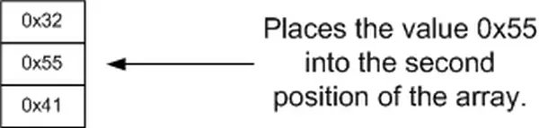
ch_array[ 1 ] = 0x55; // place 0x55 into the array
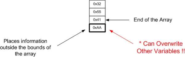
In the C language, there is no automatic verification of the index used to access an array against the size of the array. If you assign an index that attempts to access a location beyond the actual boundaries of the array, the program will access other memory locations. This behavior can result in unpredictable outcomes during program execution.
ch_array[ 3 ] = 0xAA; // attempts to place information into the array
- Why is the C language preferred for microcontrollers?
C facilitates structured development, compiles into efficient machine code, abstracts hardware intricacies, and offers software portability. - What is the primary difference between PC programs and embedded microcontroller applications?
PC programs typically return control to an operating system upon completion, whereas embedded applications lack an OS and must run continuously without idle periods. - How do flowcharts assist in software development?
Flowcharts provide visual representations of algorithms, help identify recurring tasks for function encapsulation, and serve as documentation. - What is the role of the main function in a C program?
The main function is automatically invoked when the program starts and serves as the initial task that executes other functions. - How should variables be named for better readability?
Variable names should be meaningful and descriptive, avoid capital letters reserved for constants, and start with a letter. - When should unsigned data types be used instead of signed ones?
Unsigned types are advisable for Atmel microcontrollers because they are not optimized for signed mathematical operations and unsigned types prevent negative values where unnecessary. - What happens if an 8-bit variable holds a value exceeding 255?
The most significant bit is lost, causing an inaccurate outcome known as integer overflow. - How can programmers optimize execution speed on 8-bit microcontrollers?
Programmers should use character-sized (8-bit) variables whenever feasible to minimize the number of instructions required. - What is the purpose of the #define preprocessor directive?
It establishes constants by substituting a defined name with a specific value throughout the code to enhance readability and adaptability. - How does the Do/While loop differ from the While loop?
In a Do/While loop, the condition is evaluated at the end, ensuring the loop body executes at least once regardless of the initial condition.