Summary of Reading Sensors With a Microprocessor.
This article guides users in programming a PICAXE microprocessor to read analog inputs from sensors like LDRs and thermistors, converting them into digital values to control outputs such as LEDs. It covers circuit assembly on a breadboard, the concept of Analog-to-Digital Conversion (ADC), variable storage, and essential commands like READADC, IF-THEN, PAUSE, and DEBUG for creating responsive projects like night lights or temperature alarms.
Parts used in Reading Sensors With a Microprocessor:
- Picaxe 08M2 chip
- Breadboard
- Programming adapter
- Light Dependent resistor (LDR)
- 10K resistor
- Thermistor
- DS18B20 temperature sensor
- 4K7 resistor
- LED
In my previous Instructable I showed how simple commands could be used to turn on a microprocessor output and light an LED.
https://www.instructables.com/id/Lets-Program-a-PIC…
I should stress I am not connected with Picaxe and these projects are ones I used in School to teach programming to school kids.
In the last instructable the circuit was built on breadboard which is very useful for experimentation. We will use that breadboard again for these experiments.
This time I am going to look at using some inputs and how they can be made to activate outputs.
As before all the components can be found at the Picaxe shop
http://www.picaxestore.com/index.php/en_gb/picaxe….
The additional components extra to the last instructable are:
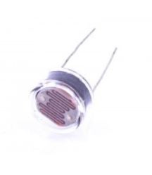
A Light Dependent resistor (LDR) £1.01 although there is a smaller one for only £0.29 which will work just as well.
A 10K resistor (`10,000 ohms – Brown Black orange) £0.72 per 100
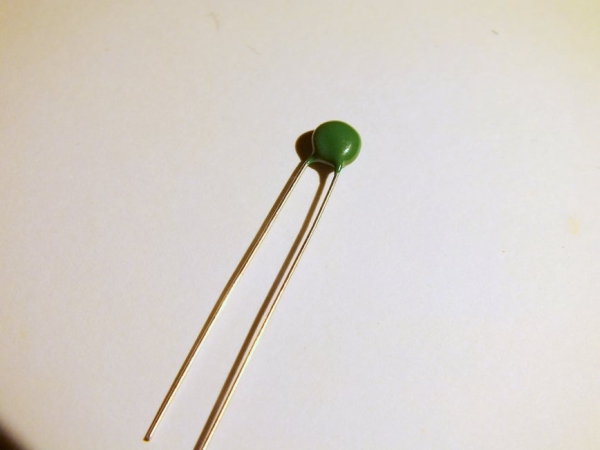
A thermistor (temperature) – £0.19
A DS18B20 temperature sensor. £2.39
A 4K7 resistor (Yellow Violet Red)
Step 1: Mounting the Components
If you followed the first instructable (and I strongly suggest you start there)
https://www.instructables.com/id/Lets-Program-a-PIC…
then you will already have the 08M2 chip and the programming adapter mounted on the breadboard.
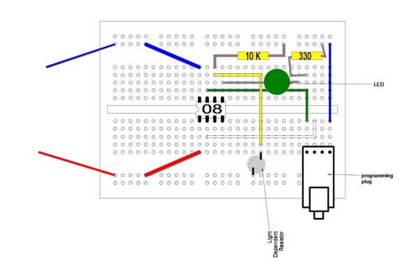
Because the breadboard is getting a little crowded I have drawn the connections above rather than photographing the actual board.
You can see that the LDR (Light Dependent resistor) is connected to + volts on one side and to the Picax leg 6 on the other side.
The LDR has no polarity so it will not matter which way it is inserted.
To make the Picaxe microprocessor register the value of the LDR it needs a 10K resistor from leg 6 to the 5 volts supply. This forms a potential divider.
To free up Leg 6 the LED has been moved to Leg 5 which is programming pin 2.
Step 2: Analogue Interface
ADC
Computers work in a digital manner, that is they understand two states, On and OFF, because these are easy to detect.
However the real world works in an analogue manner, that is things may have a wide range of values. The volume of Sound can vary from quite to loud, the intensity of Light can vary from dark to bright light.
We need a way to convert the analogue real world into the digital computer world.
A Picaxe input is usually a digital input, it is either on or off but Picaxe chips have some of their inputs that can be used to convert varying analogue values into a digital number. generally there are 2 types of conversion, the first measures the analogue input and converts it into a scale of 0 to 255.
The second measures the analogue input and converts it to a scale of 0 to 65535 and is therefor more accurate – BUT it needs more storage space in memory so unless you need this accuracy it is best to use the simpler form.
This conversion is called Analogue to Digital conversion (ADC)
Storing Numbers
Before we get to the read command lets consider how the Picaxe stores its numbers.
Number in the computing world are Binary, that is either 1 or 0. This matters not and we can still count using Binary.
Binary Decimal
0 0
1 1
10 2
11 3
100 4
101 5
110 6
111 7
1000 8
Each Binary digit is called a BIT
A group of 8 bits is called a BYTE (I am sure you have all heard of mega Bytes and Giga Bites)
A group of 16 Bits is called a word Although the length of a word can vary with different computer types, there may be 16 bits in a word or even 34 or 64 bits in a word on large mainframe computers. the longer the computer word is the more data you get every time a word is called up, a longer word can also handle bigger numbers.
In the Picaxe numbers are stored in variables, each variable has a label so it can be identified. For the Picaxe 08M2 chip there are 28 of these general purpose variables labeled B0 to B27 – Each variable can store a number up to a maximum of 255.
This is a byte variable. It is possible to deal with larger numbers but we don’t need to consider that at present. See Picaxe manuals if you need to know.
http://www.picaxe.com/Getting-Started/PICAXE-Manua…
So we can store numbers in variables Now we can do some maths with the values:-
B1= 15 will put the number 15 into memory labeled as B1
B2= 20 will put the number 20 into memory labeled as B2
B3=B1+B2 will put the number 35 into variable B3
we can read analogue values from external sensors and put that value into a variable.
So the command to read and convert an analogue value is
Readadc pin – the pin is where you are reading the value from
In our case we are using pin C.1 as the analogue input
Step 3: The Program.
Of course having assembled the hard ware we need to code the program to bring it all together.
So far we know the commands High, Low, Wait and goto
We are going to introduce the command that is used to test an input or to test the content of a variable..
This command is in the form of a statement – IF an input = something THEN jump tothis label.
In basic called an IF..Then command.
We also need to use the readadc command to fetch and convert the value seen at pin C.1 this command needs to know where to store the value it reads so we tell it put it in variable b1.
The command line is Readadc c.1,b1
In the program below we first set a label at the beginning called main:
We the do the readadc command to get the value at the LDR cell.
we put that value in variable b1.
We then check that value with the IF …then command and IF the value is greater than 50 we jump to a part of the program that will turn on an LED connected to pin c.2.
We now have a different command to wait for a time. Wait is in whole seconds whilst the PAUSE command is in 1/1000 of a second so pause 500 is half a second.
After half a second has passed we turn the LED off and go back to the main label to do the operation over again.
if the IF … THEN test isn’t true i.e the value in B1 is below 50 then we do not go to the flash routine but drop to th next command which says goto the label main to start again.
main:
Readadc C.1,b1 ; read value into b1
If b1 > 50 then flsh ; jump to flsh if b1 > 50
Goto main ; else loop back to start
flsh: high c.2 ; switch on output C.2
Pause 500 ; wait .5 seconds
Low c.2 ; switch off output C.2
Goto main ; loop back to start
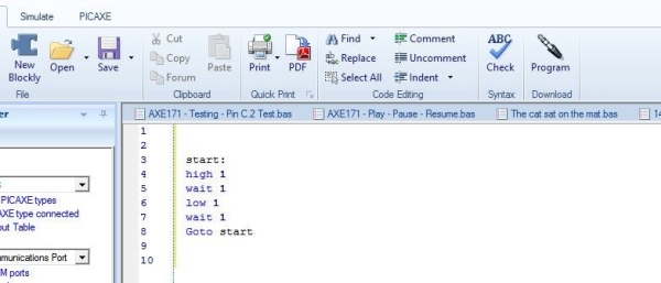
Input the program into the editor as before and download to the Picaxe 08M2 chip.
In normal room light the LED should be flashing
If you cover the LDR or turn the room light off the LED should be OFF.
With slight modification to the code this could be an alarm to show if anyone turns the lights on or moves sometime to uncover the LDR.
Step 4: Measuring Temperature Accuratly
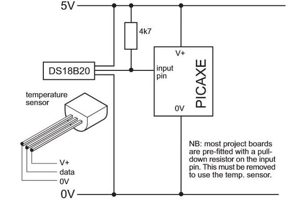
If you want to use the Picaxe to measure temperatures accurately (-55 deg C to +125 deg C) then your best bet is to buy a DS 18B20. This is a small IC – looking like a 3 wire transistor which is dedicated to measuring temperature.
This is so useful the Picaxe has a special command to read the output from this sensor.
READTEMP Pin, variable.
You need to connect the DS18B20 as in the diagrams above ensuring you have a 4K7 pull up resistor on the data line to make it read correctly.
The program is simple:
Main:
Readtemp C.1,B1
Debug B1
Goto main.
The Value in B1 is the current temp of the chip rounded to the nearest whole deg C
The DEBUG command will request the value in B1 and send it to the PC via the download cable, a window will open on the right side of the screen and the debug values of all the variables can be seen in that window.
Step 5: You Now Know, and Other Things to Do

You now have available commands:
High = Turn an output ON
Low = turn an output OFF
Wait = Do nothing for the specified number of seconds
If…Then = Check an input or a value to see what to do.
Pause = Wait for a shorter amount of time in 1/1000 of a second
Readadc = Read an analogue value and convert to digital and store in a variable.
DEBUG = Sends the value in one or several variables to the PC screen via the programming cable.
These commands can be combined to make a simple robot work and avoid obstacles (a later project).
They can make a model car park barrier operate
They can pretty much do most of the simple things you might want to do so they are very powerful.
Replace the LDR with a Thermistor and you have a system that reacts to temperature.
Using the materials you have if you have followed this so far you could:
Make a burglar alarm.
Make a night light
Make a night light that turns off after a set time
Make An automatic system to illuminate your alarm clock, the hall, the stairs, your den when it gets dark.
A Low or high temperature alarm or warning.
Source: Reading Sensors With a Microprocessor.
-
How do you convert analogue real world values into digital computer numbers?
You use Analogue to Digital conversion (ADC) which measures varying analogue inputs and converts them into a digital scale. -
What command is used to read an analogue value from a pin and store it in a variable?
The command is Readadc followed by the pin number and the variable name where the value should be stored. -
Can the Picaxe 08M2 store numbers larger than 255?
General purpose variables labeled B0 to B27 can store numbers up to a maximum of 255, though larger numbers are possible with different methods. -
What is the difference between the Wait and Pause commands?
Wait pauses execution for whole seconds while Pause waits for a shorter amount of time measured in 1/1000 of a second. -
How do you accurately measure temperatures between negative 55 and positive 125 degrees Celsius?
You should use a DS18B20 sensor with the special READTEMP command and a 4K7 pull up resistor on the data line. -
Which command sends variable values to the PC screen via the download cable?
The DEBUG command requests the value in a variable and sends it to the PC screen to display in a window. -
Does the LDR component have polarity when inserted into the circuit?
No, the LDR has no polarity so it will not matter which way it is inserted into the circuit. -
What happens if the value read from the LDR is below 50 in the example program?
If the value is below 50 the program does not jump to the flash routine but drops to the next command to loop back to the start.