Summary of ROBOT ARM Using Atmega32
This project features a 24.5-inch aluminum robotic arm with four degrees of freedom designed to play Tic-Tac-Toe. It utilizes five servo motors for movement and gripping, controlled by an ATmega32 microcontroller using forward kinematics for positioning. The arm was built as a scale model for potential delivery systems or snake arm attachments, featuring programmable motion and interactive gameplay capabilities within a five-week design timeline.
Parts used in the Robotic Arm Tic-Tac-Toe Project:
- Aluminum (8975K22)
- Aluminum (8975K91)
- Aluminum (9008K151)
- Turn Table (6031K16)
- Bearings (57155K352)
- Dowel Pins (90145A508)
- Machine Screws (91771A126)
- Set Screws (92778A117)
- HS5955-TG Servos
- Gripper (358811)
- Servo Extenders
- STK 500
- Mega 32
- 330 Resistor
- 1K Resistor
- 1 M Resistor
- Phototransistor (4n35)
- White Board
- Diodes (1N4001)
- 16 MHz Crystal
- 6.4V 2.0 Amps Power Supply
- Wood Table Top
- Wood Mount
Introduction
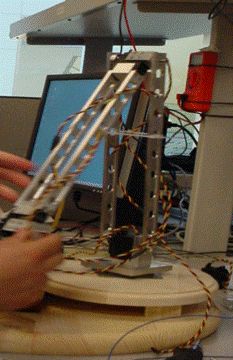
Our project is a twenty four and half inch aluminum frame robotic arm with four degrees of freedom.
In our project we made the arm the second player in the classic game of Tic-Tac-Toe to demonstrate its programmable repeatable motion. The arm consists of five servo motors, four to control the motion and one to control the end effecter (gripper). The arm moves tic-tac-toe pieces onto a board for its opponent and itself to give the user interactive control over the arm.
This project was a five week design project for ECE 476. Video of the arms ranging from motion, game play, and feats of strength are below in the results section.
High Level Design
Rationale
We are both members of the CU Snake Arm team so we were aware that the 2008 CU Snake Arm was lacking a delivery vehicle. Typical snake arms are attached to industrial robotic arms. So we both thought that it would be nice to build a scale model for a possible delivery system or a possible end attachment for a future snake arm.
Background Math
This project does not implement inverse kinematics calculation on the mcu but we did make use of forward kinematics to aid in programming position. The forward kinematics determines the location and angle of the end effecter. To begin the calculation find the position of the first joint (x1,y1). Assuming that the turntable is at position (x0,y0) and the length of the segments of the arm are L1 and L2 receptivity the calculations go as follows.
x1= L1cos(theta1) + x0
y1 =L1sin(theta1) + y0
The position of the second joint is given by:
x2 =x1 + L2cos(180-theta1-theta2)
y2= y2 + L2sin(180-theta1- theta2)
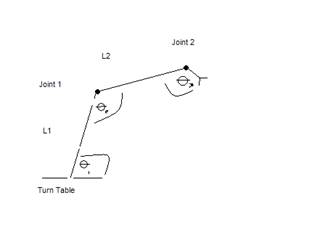
We define the angles to be those formed by two segments next to another, making them more easily observed. Theta3 in our project was desired to be perpendicular to the horizontal axis and was (270 –theta1 –theta2) in the first quadrant.
Patents, Copyrights and Trademarks
Although a servo controlled robotic arm and Tic-Tac-Toe are not new ideas, there are no patent, copyright, or trademark issues involved with the project. The arm was designed by the CU Snake Arm Team.
Program/Hardware Design
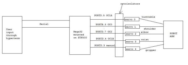
Logical Structure
The logical structure of the design is shown below:
Mechanical Details
Below is a CAD picture of the arm. The complete CAD assembly and part files are in appendix B. These files contain all the measurement data. The parts for the arm were machined in Emerson Lab at Cornell University. The completed arm was just screwed to a table top to act as a base.
Hardware/Software Tradeoffs
The hardware tradeoffs we were considering involved the use of Hitec-5995TG servo motors with an average holding torque limit of approximately 2.2 ft lbs, as opposed to perhaps building a smaller arm with less powerful motors which would require less voltage to operate. We decided to go with the larger arm which was just within the limit of the more powerful servos. To get the power supply voltage at least up to 6 V, we decided to use a 6.4 V, 2 A current DC adapter.
The software tradeoff involved thinking about whether we needed to create manual PWM waveforms with a delay of at least 20 ms between pulses or use the in-built timers in the Mega32. For the most part we decided to use the timers because we discovered that it didn’t make any difference as to what delay we supplied between pulses. However, we ran out of timers to use once we got to servo 4, and so we had to generate a manual PWM waveform for the gripper servo.
Standards
The applicable standards were set by our own snake arm team. Any robotic arm built by us would have to use servo motors, and would have to have repeatable control with programmability.
Parts List:
| Item | Part # | Quantity | Price | Total Price | Location |
| Aluminum | 8975K22 | 1 | 11.24 | 11.24 | McMaster |
| Aluminum | 8975K91 | 1 | 11.59 | 11.59 | McMaster |
| Aluminum | 9008K151 | 1 | 16.90 | 16.90 | McMaster |
| Turn Table | 6031K16 | 1 | 1.87 | 1.87 | McMaster |
| Bearings | 57155K352 | 3 | 7.50 | 22.50 | McMaster |
| Dowel Pins (10) | 90145A508 | 1 | 6.37 | 6.37 | McMaster |
| Machine Screws (30) | 91771A126 | 1 | 6.18 | 6.18 | McMaster |
| Set Screws (25) | 92778A117 | 1 | 6.18 | 6.18 | McMaster |
| HS5955-TG Servos | ———— | 5 | Borrowed ( $85) |
———— | Snake Arm |
| Gripper | 358811 | 1 | 14.85 | 14.85 | RobotStore.com |
| Servo Extenders | ———— | 4 | Borrowed | ———— | Snake Arm |
| STK 500 | ———— | 1 | Rent | 15 | 476 Lab |
| Mega 32 | ———— | 1 | Rent | 8 | 476 Lab |
| 330 Resistor | ———— | 5 | ———— | ———— | 476 Lab |
| 1K Resistor | ———— | 5 | ———— | ———— | 476 Lab |
| 1 M Resistor | ———— | 5 | ———— | ———— | 476 Lab |
| Phototransistor | 4n35 | 5 | ———— | ———— | 476 Lab |
| White Board | ———— | 1 | ———— | ———— | 476 Lab |
| Diodes | 1N4001 | 5 | ———– | ———– | 476 Lab |
| 16 MHz Crystal | ———— | 1 | ———— | ———— | 476 Lab |
| 6.4V 2.0 Amps Power Supply | ———— | 1 | Borrowed | ———— | Snake Arm |
| Wood Table Top | ———— | 1 | 10 | 10 | Lowes |
| Wood Mount | ———— | 1 | 7 | 7 | Walmart |
| Total | 131.31 |
For more detail: ROBOT ARM Using Atmega32
- How many degrees of freedom does the robotic arm have?
The arm has four degrees of freedom. - What is the primary function of the fifth servo motor?
The fifth servo motor controls the end effector, which acts as the gripper. - Does the project implement inverse kinematics on the microcontroller?
No, the project does not implement inverse kinematics calculation on the MCU but uses forward kinematics instead. - Which microcontroller was used to control the arm?
An ATmega32 microcontroller was used for the project. - What type of servo motors were selected for the hardware design?
Hitec-5995TG servo motors with an average holding torque limit of approximately 2.2 ft lbs were used. - How was power supplied to the system?
A 6.4 V, 2 A current DC adapter was used to supply at least 6 V to the servos. - Why was a manual PWM waveform generated for one servo?
A manual PWM waveform was generated for the gripper servo because the team ran out of timers after controlling the first four servos. - Where were the parts for the arm machined?
The parts were machined in the Emerson Lab at Cornell University.