Summary of Scrolling Text Display on 8×8 LED Matrix using AVR Microcontroller
This tutorial outlines the design of an 8x8 LED matrix scrolling display using an ATMEGA32 microcontroller. The project involves soldering 64 LEDs onto a perfboard to create rows and columns, controlled by a C program written in ATMEL STUDIO. The system powers specific row positive terminals and grounds column negative terminals to scroll alphabets across the matrix.
Parts used in the 8x8 LED Matrix Scrolling Display:
- ATMEGA32
- Power supply (5v)
- 64 LEDs
- 1KΩ resistors (8 pieces)
- AVR ISP Programmer
- Perfboard with other soldering tools
- ATMEL STUDIO 6.1
In this tutorial we are going to design an 8×8 LED Matrix Scrolling Display using ATMEGA32, which will show scrolling alphabets.
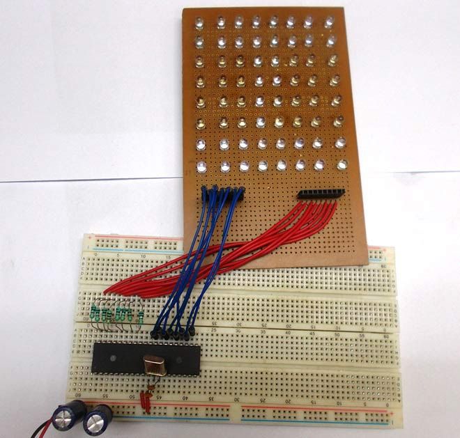
8×8 LED Matrix contains 64 LEDs (Light Emitting Diodes) which are arranged in the form of a matrix, hence the name is LED matrix. We are going to make this Matrix by soldering 64 LEDs on to the perfboard or DOT PCB. The LEDs can be of any color, choose the ones which are available with you. Then we will write a C program for ATmega32 AVR Microcontroller to control these 64 LEDs matrix. The ATmega, according to program, powers appropriate LEDs to show characters in scrolling fashion. We have previously done same Scrolling Text project with Arduino.
Components Required:
- ATMEGA32
- Power supply (5v)
- 64 LEDs
- 1KΩ resistors (8 pieces),
- AVR ISP Programmer
- Perfboard with other soldering tools
- ATMEL STUDIO 6.1
Circuit and Working Explanation:
There are 64 LEDs arranged in a matrix form. So we have 8 columns and 8 rows. Over those rows and columns, all the positive terminals in a row are brought together. For each row, there is one Common Positive Terminal for all 8 LED in that row. It is shown in below figure,
So for 8 rows we have 8 common positive terminals. Consider the first row, as seen in the figure, 8 LEDs from D57 to D64 have a common positive terminal and are denoted by ‘POSITIVE0’. Now if we want glow one or all LEDs in the first ROW of matrix, then we should power the A0 of LED Matrix. Likewise if we want to glow any LED (or all) in any ROW then we need to power the corresponding Common Positive Terminal Pin of that respective Row.
This is not over yet and just leaving the MATRIX ROWS with positive supply will not yield anything. We need to ground the LEDs negatives to glow them. So in 8×8 LED matrix, all the negative terminals of the LEDs in any column are brought together to form eight Common Negative Terminals, like all the negative terminals in first column are connected together to the C7 (NEGATIVE7).
For more detail: Scrolling Text Display on 8×8 LED Matrix using AVR Microcontroller
- How is the 8x8 LED matrix constructed?
The matrix is made by soldering 64 LEDs onto a perfboard or DOT PCB. - Can any color LEDs be used for this project?
Yes, you can choose LEDs of any color that are available to you. - What language is used to control the LEDs?
A C program is written for the ATmega32 AVR Microcontroller to control the LEDs. - How many common positive terminals are required?
There are 8 common positive terminals, one for each of the 8 rows. - How are the negative terminals connected in the matrix?
All negative terminals in any column are brought together to form eight Common Negative Terminals. - Which software is needed to write the program?
ATMEL STUDIO 6.1 is required to write the C program. - Does the project require an external programmer?
Yes, an AVR ISP Programmer is listed as a required component. - What is the total number of LEDs used in the matrix?
The matrix contains exactly 64 Light Emitting Diodes arranged in a grid.